Sintered body, arc tube, and manufacturing method of sintered body

Inactive Publication Date: 2007-10-18
NGK INSULATORS LTD
View PDF11 Cites 4 Cited by
  • Summary
  • Abstract
  • Description
  • Claims
  • Application Information

AI Technical Summary

Benefits of technology

[0009] Furthermore, in the method described in Patent Document 3, since a meltable binder is used, the molded body is easily deformed during bonding or in the degreasing process. In this technique, bonding is performed by heating the junction. However, it is substantially impossible to restrict a buffer zone to the junction interface only, and a region extending several millimeters from the junction is deformed, and develops a buffer effect. Consequently, the shape is easily changed, and deformed portions have a significantly increased thickness, resulting in a decrease in transmittance. Furthermore, since a process of subjecting the joint surfaces of two molded bodies to compression / expansion is required, the production cost is increased. In particular, when thin portions of two molded bodies are butt-joined to each other, it is extremely difficult to perform the compression / expansion process on the joint surface. Furthermore, molded bodies to be bonded are obtained substantially by wax extrusion, and since dewaxing is time-consuming, there is a decrease in productivity. Furthermore, in the method according to Patent Document 3, the junction tends to swell or deform, and also, because of repeated stress occurring in the compression / expansion process, the surface of the junction may become roughened as the material swells. As a result, there is a possibility that the surface roughness of the junction may increase or the translucency of the junction may decrease. Furthermore, for example, when swelling or deformation of the junction is decreased to prevent the decrease in translucency, defects easily occur during melt integration of molded bodies, resulting in a decrease in the strength of the joined body.
[0010] It is an object of the present invention to provide methods for manufacturing a joined body of inorganic powder-molded bodies, a sintered body, and an arc tube, in which defects at the junction can be suppressed or avoided. It is another object of the present invention to provide a sintered body excellent in terms of the surface roughness, transparency, or surface smoothness of the junction, and an arc tube including the sintered body.

Problems solved by technology

However, in the method in which a plurality of parts are separately formed, and the different parts are fitted together and integrally sintered using a difference in firing shrinkage ratio, the steps are complicated, and it is difficult to improve productivity.
In the gel-casting methods described in Patent Documents 1 and 2, it is difficult to achieve both high shape accuracy and high productivity.
However, it is substantially impossible to restrict a buffer zone to the junction interface only, and a region extending several millimeters from the junction is deformed, and develops a buffer effect.
Consequently, the shape is easily changed, and deformed portions have a significantly increased thickness, resulting in a decrease in transmittance.
Furthermore, since a process of subjecting the joint surfaces of two molded bodies to compression / expansion is required, the production cost is increased.
In particular, when thin portions of two molded bodies are butt-joined to each other, it is extremely difficult to perform the compression / expansion process on the joint surface.
Furthermore, molded bodies to be bonded are obtained substantially by wax extrusion, and since dewaxing is time-consuming, there is a decrease in productivity.
Furthermore, in the method according to Patent Document 3, the junction tends to swell or deform, and also, because of repeated stress occurring in the compression / expansion process, the surface of the junction may become roughened as the material swells.
As a result, there is a possibility that the surface roughness of the junction may increase or the translucency of the junction may decrease.
Furthermore, for example, when swelling or deformation of the junction is decreased to prevent the decrease in translucency, defects easily occur during melt integration of molded bodies, resulting in a decrease in the strength of the joined body.

Method used


Image

  • Sintered body, arc tube, and manufacturing method of sintered body
  • Sintered body, arc tube, and manufacturing method of sintered body
  • Sintered body, arc tube, and manufacturing method of sintered body

Examples


example 1

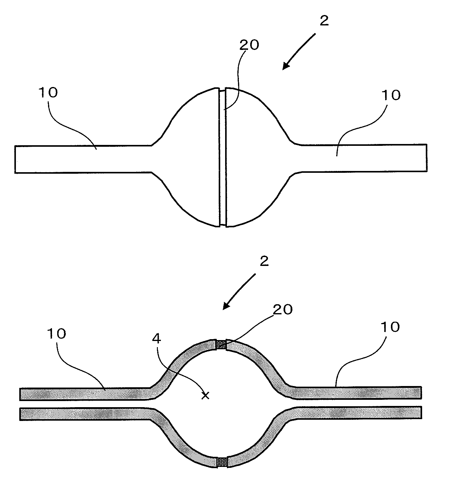
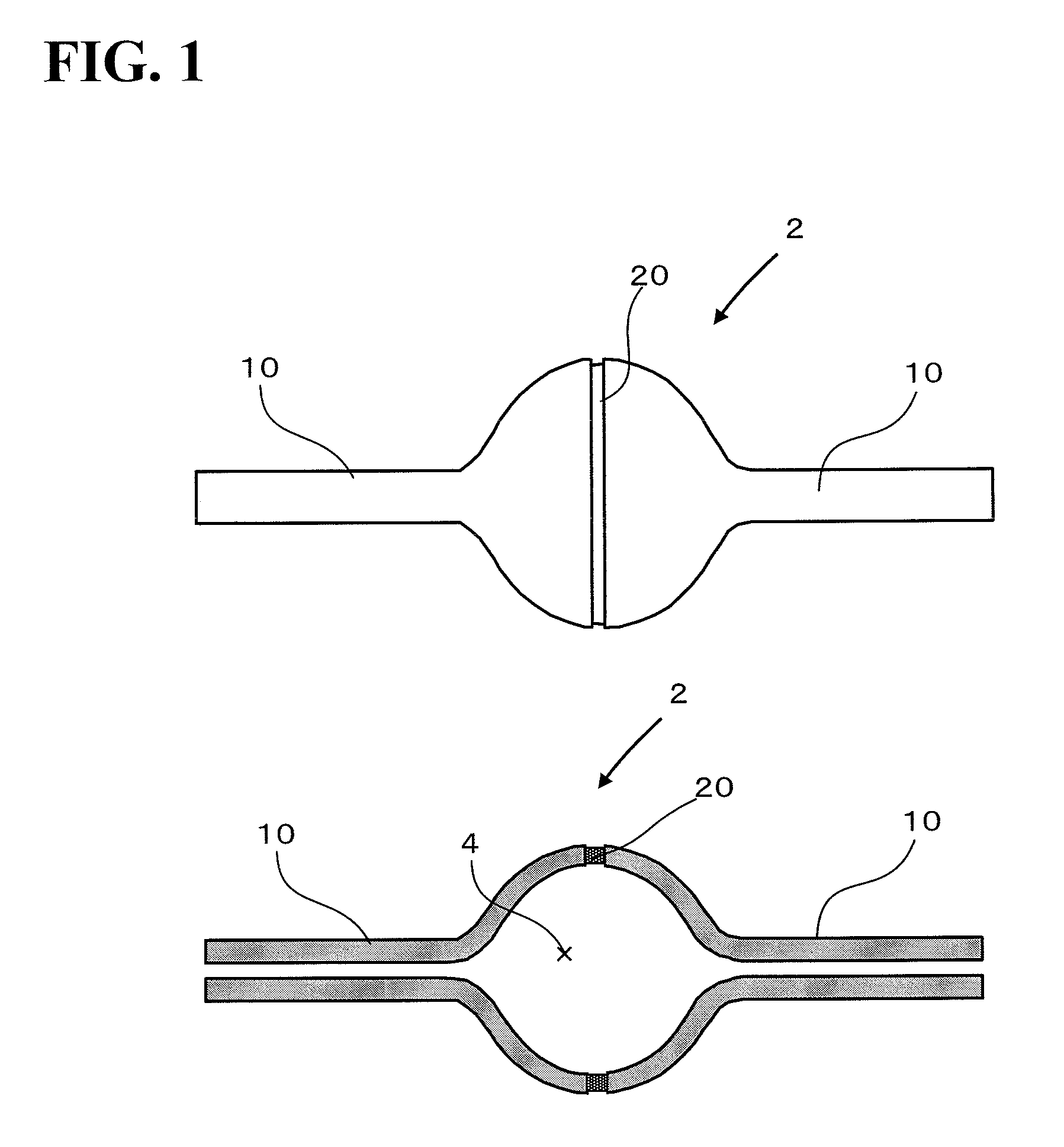
[0101] In this example, an arc tube was produced as a sintered body. A molded body constituting the sintered body was formed by the method described below. That is, 100 parts by weight of alumina powder (trade name: Alumina AES-11C, manufactured by Sumitomo Chemical Company) and 0.025 parts by weight of magnesia, as starting material powder, 24 parts by weight of dimethyl malonate as a dispersion medium, 2 parts by weight of Bayhydur 3100 (trade name, manufactured by Bayer-Sumitomo Urethane K.K.) as a gelling agent, 1 part by weight of MALIALIM AKM0351 (trade name, manufactured by NOF Corporation) as a dispersant, and 0.2 parts by weight of triethylamine as a catalyst were mixed. The resulting slurry was poured into an aluminum alloy mold, and the cast slurry was left to stand at room temperature for one hour and then at 40° C. for 30 minutes to carry out solidification, followed by mold releasing. The solidified pieces were left to stand at room temperature and at 90° C., respectiv...

example 2

[0108] In Example 2, an arc tube was produced as a sintered body. A molded body constituting the sintered body was formed by the method described below. That is, 100 parts by weight of alumina powder (trade name: Alumina AKP-20, manufactured by Sumitomo Chemical Company) and 0.025 parts by weight of magnesia, as starting material powder, 27 parts by weight of Chemrez 6080 (trade name, manufactured by Hodogaya Ashland Co., Ltd.) and 0.3 parts by weight of ethylene glycol, as a dispersion medium, 4 parts by weight of SBU Isocyanate 0775 (trade name, manufactured by Bayer-Sumitomo Urethane K. K.) as a gelling agent, 3 parts by weight of MALIALIM AKM0351 (trade name, manufactured by NOF Corporation) as a dispersant, and 0.1 parts by weight of Kaolizer No. 25 (trade name, manufactured by Kao Corporation) as a catalyst were mixed. The resulting slurry was poured into the same mold as that in Example 1, and the cast slurry was left to stand at room temperature for one hour and then at 40° ...

example 3

[0112] A sintered body A of Example 3 was obtained as in Example 2 except that the amount of magnesia in the bonding slurry was 0.020 parts by weight. The thermal shock resistance of the sintered body A of Example 3 was evaluated by the water quenching method. As a result, no cracks occurred in the sintered body A even at 150° C. Furthermore, with respect to the sintered body A, after the evaluation of thermal shock resistance, the amount of He leak at the middle part was measured by a He leak detector. The amount of leak was 1×10⁻⁸ atm·cc / sec or less. Furthermore, in Example 3, the average grain diameter in the sintered molded body portion was 24.3 μm, and the average grain diameter in the vicinity of the center in the width direction of the sintered junction portion was 47.5 μm. The average grain diameter in the vicinity of a position at a distance of 150 μm from the center in the width direction of the sintered junction portion toward the sintered molded body portion was 34.1 μm....


PUM

PropertyMeasurementUnit
Lengthaaaaaaaaaa
Fractionaaaaaaaaaa
Widthaaaaaaaaaa

Abstract

The present invention provides a sintered body of a joined body including two or more inorganic powder-molded bodies. The sintered body includes first components corresponding to the two or more inorganic powder-molded bodies in the joined body; and a second component corresponding to a junction in the joined body, and has one or both of the features (a) and (b): (a) the second component has a surface roughness equal to or lower than that of each of the first components; and (b) the second component has, in the vicinity of a width center thereof, a transmittance equal to or higher than that of each of the first components.

Description

BACKGROUND OF THE INVENTION [0001] 1. Field of the Invention [0002] The present invention relates to a sintered body in which a plurality of inorganic powder-molded bodies are integrated, an arc tube, and a method for manufacturing the sintered body. [0003] 2. Description of the Related Art [0004] Ceramics, refractory metals, and ceramic-metal composites are usually manufactured by sintering starting material powders, and thus, shape forming of a product is performed mainly at the time of molding. However, ease of shape-forming depends on the molding method employed. For example, a disc-shaped product is easily formed using a mold-pressing method. In the case of a product with a complicated shape, a method is used in which a bulk body is compressed into a preform by means of cold isostatic press (CIP), and then a shape is formed by machining. [0005] Gel-casting is a method in which a liquid slurry containing inorganic powder is solidified by a chemical reaction between organic compo...

Claims


Application Information

Patent Timeline
IPC IPC(8): B22F7/00B32B9/00
CPCC04B35/115H01J61/302C04B35/62655C04B35/632C04B35/6342C04B37/005C04B2235/3206C04B2235/6023C04B2235/6582C04B2235/661C04B2235/786C04B2235/94C04B2235/963C04B2235/9653C04B2235/9661C04B2237/064C04B2237/343C04B2237/55C04B2237/708C04B2237/76C04B2237/765C04B2237/78H01J9/247C04B35/6264
Inventor YOSHIOKA, KUNIHIKOMATSUMOTO, KAZUHIOHASHI, TSUNEAKIINOUE, MASAKATSUIKAMI, TOSHIICHIWATANABE, KEIICHIRO
Owner NGK INSULATORS LTD
Why Eureka
Try Eureka