
Apparatus for rejecting image in receiver

Inactive Publication Date: 2011-07-28
KOREA ADVANCED INST OF SCI & TECH
View PDF3 Cites 8 Cited by
  • Summary
  • Abstract
  • Description
  • Claims
  • Application Information

AI Technical Summary

Benefits of technology

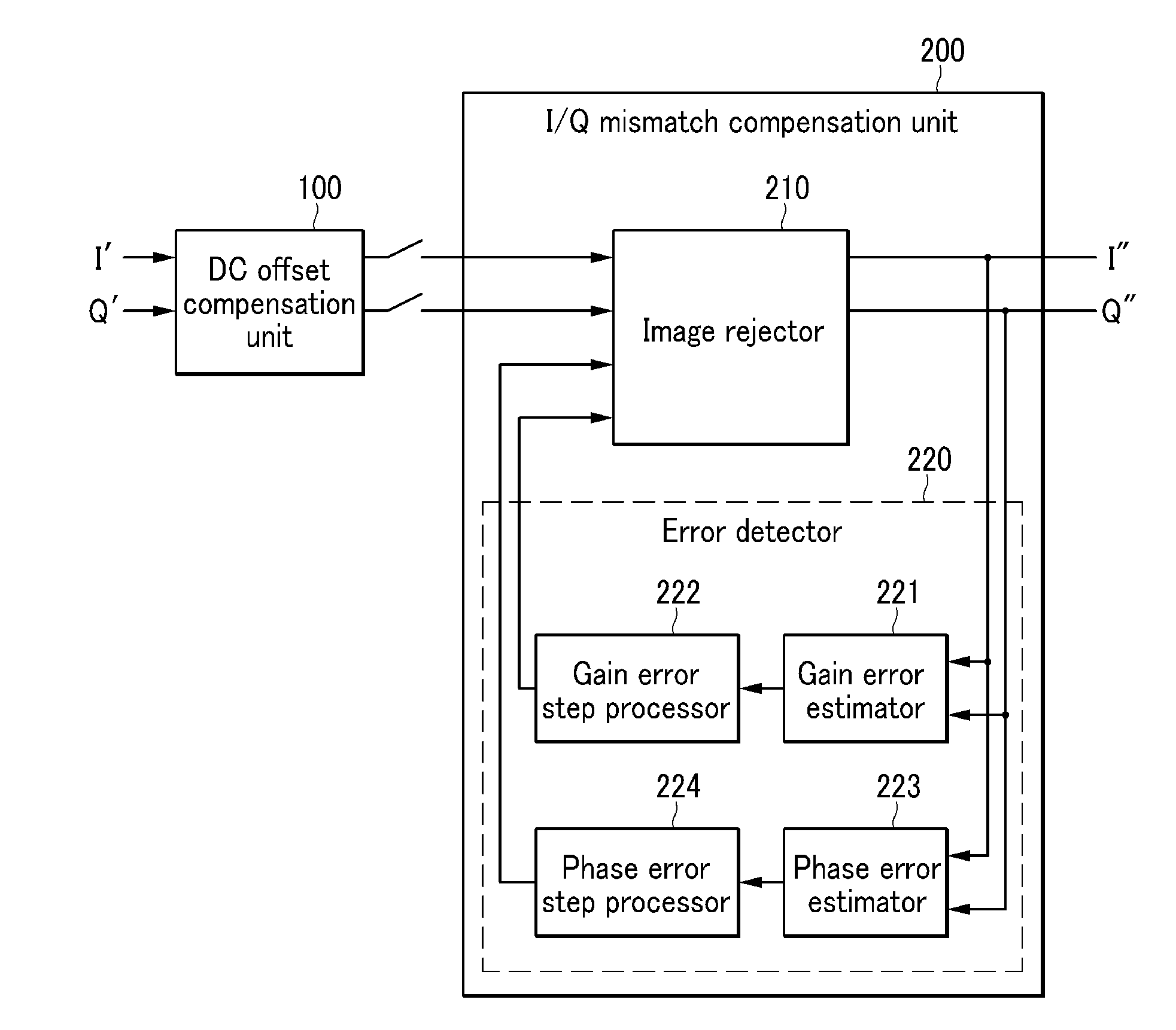
[0024]The present invention has been made in an effort to provide an image rejection apparatus having advantages of increasing the image rejection ratio and reducing the adaptation time taken to obtain a high image rejection ratio by solving a problem, such as imperfection in the analog structure, and a problem in which the image rejection ratio is restricted by the influence of DC components in the digital structure.
[0025]To achieve the technical object, an apparatus for rejecting images according to an aspect of the present invention is an apparatus for rejecting image signals in a receiver of a direct conversion structure and comprises a signal mismatch compensation unit configured to detect gain error and phase error between an In-phase (I) signal and a Quadrature (Q) signal received through the receiver, to reject image signals existing in the I and Q signals, and to output a result. The signal mismatch compensation unit detects the gain error and the phase error using an adaptive step method of reducing the step size of the gain error and the phase error step by step whenever the gain error and the phase error are converged.
[0028]According to the present invention, high image rejection ratio is achieved and the adaptation time taken to obtain a high image rejection ratio is reduced simultaneously.
[0029]Further, a bad influence of the DC offset on the image rejection ratio can be prevented by removing DC offset signals in a digital structure, accordingly, error can be accurately estimated.

Problems solved by technology

During such a down-conversion process, image signals are generated in signal bands because of I / Q path gain and phase errors.
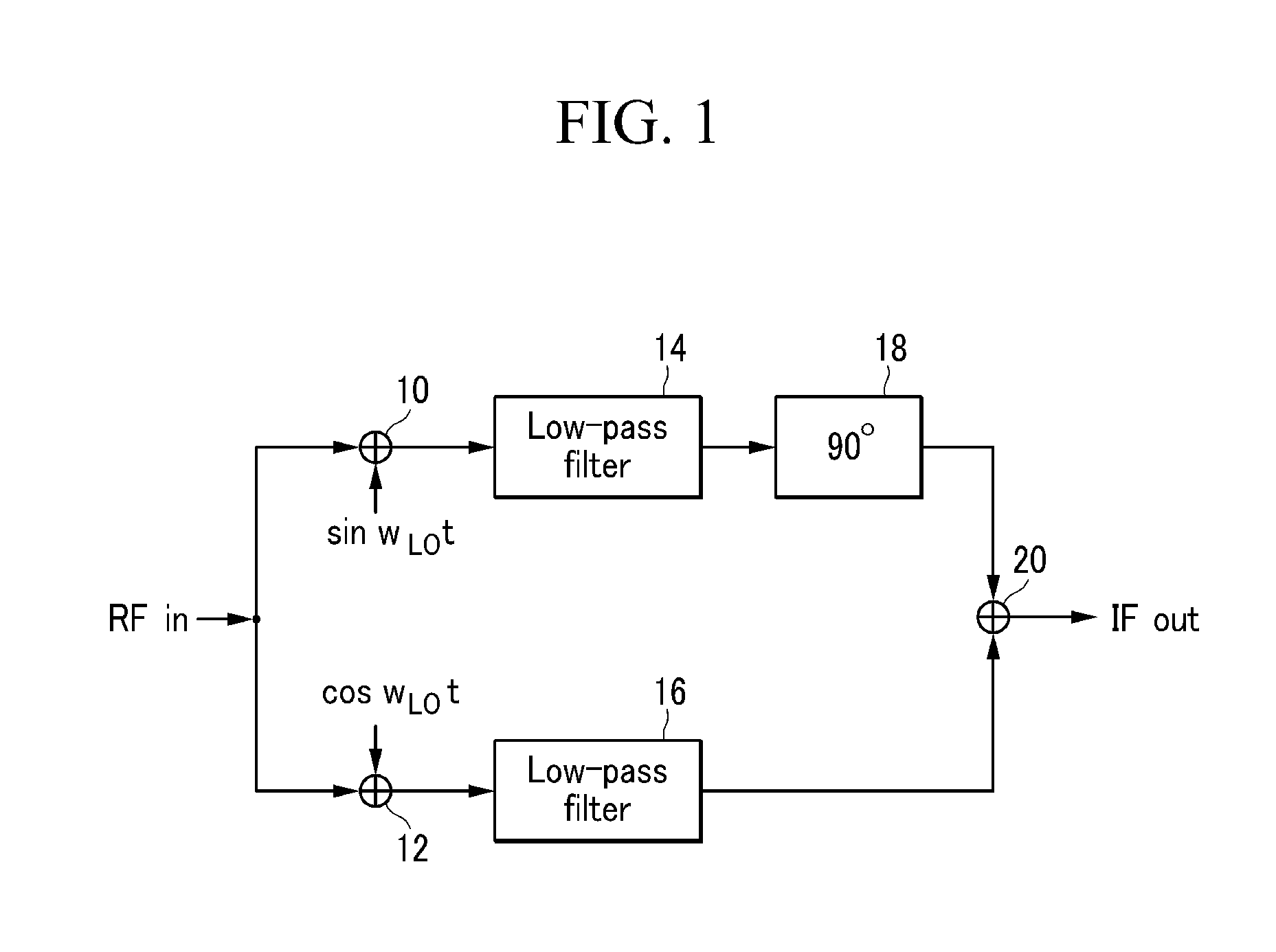
The above-described image rejection apparatus of a Hartley architecture is problematic in that image signals are not fully rejected if gain error or phase error occurs between the two paths due to variation in the process or a change in the channel because it includes analog circuits.
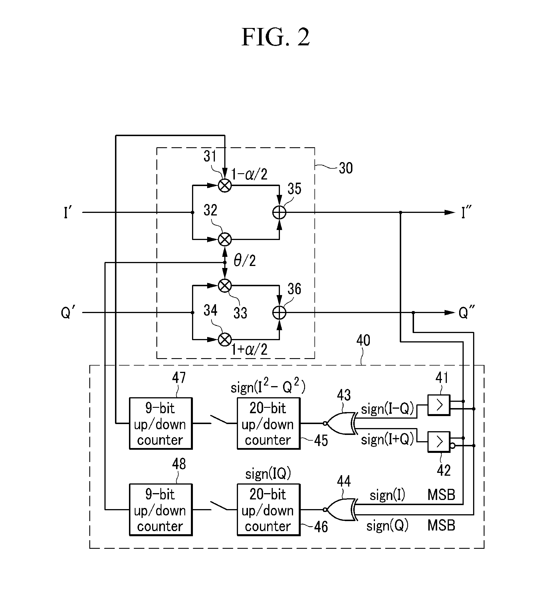
Referring to FIG. 2, the above-described image rejection apparatus is advantageous in that it has a simple construction because simple hardware is used to reject images on signals, but is problematic in that the adaptation time is long in order to obtain a high image rejection ratio because the size of a step must be small for accurate error estimation.
Further, the image rejection apparatus of FIG. 2 is configured to accumulate errors at DC and is problematic in that, if signals or offset exists at DC, the image rejection ratio is lowered because error cannot be accurately estimated.

Method used


Image

  • Apparatus for rejecting image in receiver
  • Apparatus for rejecting image in receiver
  • Apparatus for rejecting image in receiver

Examples


Embodiment Construction

[0039]In the following detailed description, only certain exemplary embodiments of the present invention have been shown and described, simply by way of illustration. As those skilled in the art would realize, the described embodiments may be modified in various different ways, all without departing from the spirit or scope of the present invention. Accordingly, the drawings and description are to be regarded as illustrative in nature and not restrictive. Like reference numerals designate like elements throughout the specification.

[0040]In the entire specification, unless explicitly described to the contrary, the word “comprise” and variations such as “comprises” or “comprising”, will be understood to imply the inclusion of stated elements but not the exclusion of any other elements. Further, the terminologies described in the specification, such as “unit”, “ . . . er(or)”, and “module”, refer to units performing at least one function or operation, which can be implemented by hardwa...


PUM


Abstract

The present invention relates to an apparatus for rejecting images in a receiver.The apparatus of the present invention relates to an apparatus for rejecting image signals in a receiver of a direct conversion structure and comprises a signal mismatch compensation unit configured to detect gain error and phase error between an In-phase (I) signal and a Quadrature (Q) signal received through the receiver, to reject image signals existing in the I and Q signals, and to output a result. The signal mismatch compensation unit detects the gain error and the phase error using an adaptive step method of reducing the step size of the gain error and the phase error step by step whenever the gain error and the phase error are converged.According to the present invention, high image rejection ratio is achieved and the adaptation time taken to obtain a high image rejection ratio is reduced simultaneously. Further, a bad influence of the DC offset on the image rejection ratio can be prevented by removing DC offset signals in a digital structure, accordingly, error can be accurately estimated.

Description

BACKGROUND OF THE INVENTION[0001]1. Field of the Invention[0002]The present invention relates to a receiver of a direct conversion structure. More particularly, the present invention relates to an image rejection apparatus capable of rejecting an image signal interfering with an original signal using a sign-sign Least Mean Square (LMS) algorithm having an adaptive step size in the case in which there is a mismatch between In-phase (I) / Quadrature (Q) signal paths in a quadrature receiver of a direct conversion structure.[0003]2. Description of the Related Art[0004]In a receiver of a direct conversion structure, Radio Frequency (RF) signals are down-converted into Intermediate Frequency (IF) signals using complex I / Q mixers not having an image filtering function. During such a down-conversion process, image signals are generated in signal bands because of I / Q path gain and phase errors.[0005]An image rejection apparatus also called a Hartley architecture, which is one of conventional ...

Claims


Application Information

Patent Timeline
IPC IPC(8): H04L27/08
CPCH03D3/009H03D7/166H04L27/3863H04B1/30H03D7/18
Inventor KIM, SUN A.YOON, DAE-YOUNGLEE, SANG-GUGPARK, HYUNG-CHULLEE, JEONGSEON
Owner KOREA ADVANCED INST OF SCI & TECH
Learn More