Improved tissue supporting devices

a technology of tissue supporting and supporting device, which is applied in the field of tissue supporting device, can solve the problems of balloon expandable stents not always expanding uniformly around their circumference, tearing the covering or coating, and unable to achieve consistent healing

Inactive Publication Date: 2011-07-28
BOSTON SCI SCIMED INC
View PDF99 Cites 27 Cited by
  • Summary
  • Abstract
  • Description
  • Claims
  • Application Information

AI Technical Summary

Benefits of technology

[0012] In one embodiment, a first portion is a resilient spring-like metal for self-expansion and a second portion is a deformable metal for final sizing. In a more preferred shape memory embodiment, a first portion is a self-expanding austenitic one and a second is a martensitic one capable of deformation. In the case of shape memory embodiments the “portions” may be discrete or merely different phases of an alloy.
[0013] The most preferred embodiment of the invention is a stent,

Problems solved by technology

Balloon expandable stents do not always expand uniformly around their circumference.
As a result, healing may not take place in a consistent manner.
If the stent is coated or covered, non-uniform expansion may tear the covering or coating.
Additionally, long stents of this type

Method used


Image

  • Improved tissue supporting devices
  • Improved tissue supporting devices
  • Improved tissue supporting devices

Examples


Embodiment Construction

[0032] Preferred embodiments of this invention are described below with particular reference to the accompanying drawing Figures.

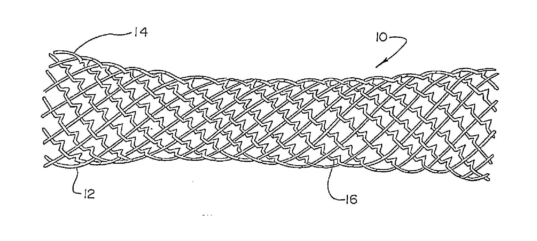
[0033] Referring first to the embodiment shown in FIG. 1, a stent 10 is shown comprised of braided or interwoven metal strands 12 and 14. Strands 12 are of a resilient spring-like metal such as spring steel, Elgiloy for example. Preferably, strands 12 are spirally extending in the same direction, spiraling to the right as seen in FIG. 1. Strands 14 are of a deformable or annealed metal such as stainless steel and are preferably spiraled in the opposite direction as strands 12, as shown in FIG. 1.

[0034] Given such a stent construction of two components i.e., strands 12 and. 14, it can be seen that stent 10 may be readily loaded on a catheter as by placing it over an uninflated balloon on a balloon catheter and compressing it tightly around the balloon and then placing a sheath over the stent to hold it in place during the transluminal placement procedure....


PUM


Abstract

A new multiple component stent arrangement which allows for initial self-expansion and subsequent deformation to a final enlarged size.

Description

CROSS-REFERENCE TO RELATED APPLICATIONS [0001] This application is a Continuation application from Ser. No. 09 / 427,291, filed on Oct. 26, 1999, which is a Continuation application from Ser. No. 08 / 737,492 filed on May 18, 1995, as a §371 of PCT / US95 / 06228 filed May 18, 1995, the contents of which is hereby incorporated by reference, now U.S. Pat. No. 6,582,461, which is a continuation-in-part of application Ser. No. 08 / 246,320, filed May 19, 1994. This application is also a continuation of application Ser. No. 09 / 172,590 filed on Oct. 14, 1998, now 6,451,052, which is a Division of application Ser. No. 08 / 737,492 filed on May 18, 1995, as a §371 of PCT / US95 / 06228 filed May 18, 1995, now U.S. Pat. No. 6,582,461, which is a continuation-in-part of application Ser. No. 08 / 246,320, filed May 19, 1994.BACKGROUND OF THE INVENTION [0002] This invention relates to tissue supporting devices in general and most particularly to vascular stents for placement in blood vessels. A primary feature ...

Claims


Application Information

Patent Timeline
IPC IPC(8): A61F2/06A61F2/00A61F2/88A61F2/90A61L31/02
CPCA61F2/844A61F2220/0075A61F2/90A61F2/91A61F2/915A61F2002/91533A61F2002/9155A61F2002/91558A61F2002/91575A61F2210/0019A61F2250/0029A61F2250/0042A61L31/022A61F2210/0076A61F2/88
Inventor BURMEISTER, PAULEUTENEUER, CHARLESBROWN, BRIANFORDENBACHER, PAULVRBA, ANTHONY
Owner BOSTON SCI SCIMED INC
Why Eureka
Try Eureka