Multi-directional mounting faceplate

Active Publication Date: 2011-08-04
EMCOM TECH
View PDF7 Cites 7 Cited by
  • Summary
  • Abstract
  • Description
  • Claims
  • Application Information

AI Technical Summary

Benefits of technology

[0010]In one embodiment, bumps are formed at two opposite ends of the linking plate so that the nose cover can be selectively engaged with the faceplate body from different sides of the opening. The linking plate further includes a stopper and a groove, wherein the groove is formed between the stopper and the bump. The stopper vertically extends upward from the surface of linking plate to limit the moving range of the nose cover in the open direction of the opening. The groove is formed surrounding the bump so that the bump has certain flexibility. In one embodiment, the bump has only one side connected to the linking plate to allow the bump to be flexible. The bump is a raised part protruding from the surface of the linking plate. The faceplate body is further formed wit

Problems solved by technology

For the case that no sufficient space is provided inside the wall or the transmission lines of audio and video devices need to

Method used


Image

  • Multi-directional mounting faceplate
  • Multi-directional mounting faceplate
  • Multi-directional mounting faceplate

Examples


Embodiment Construction

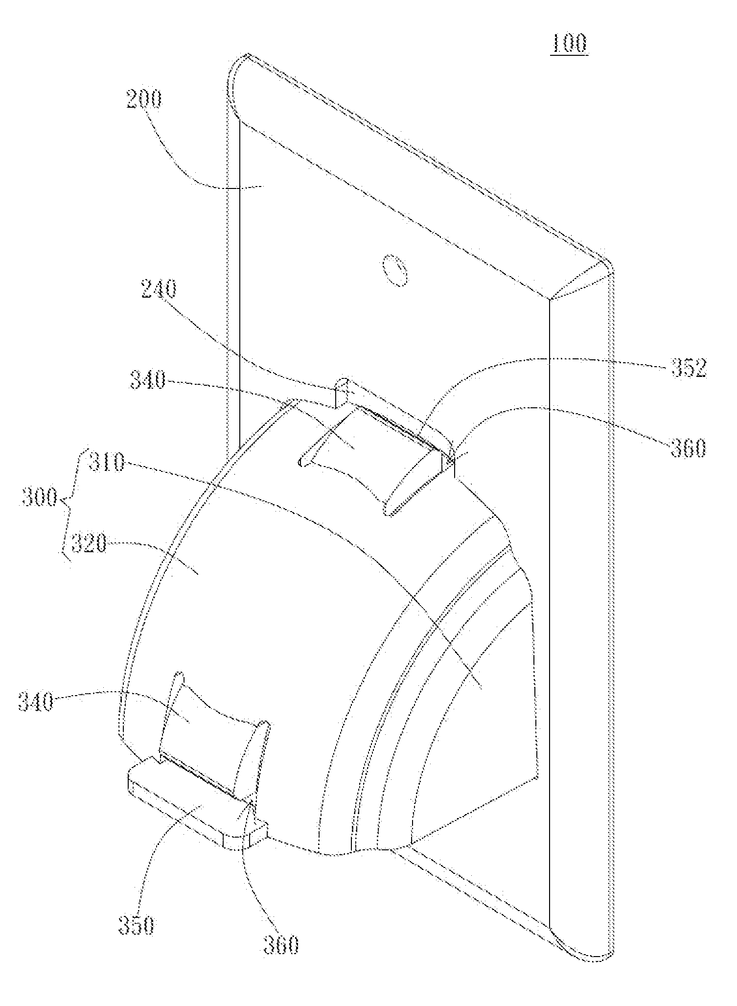
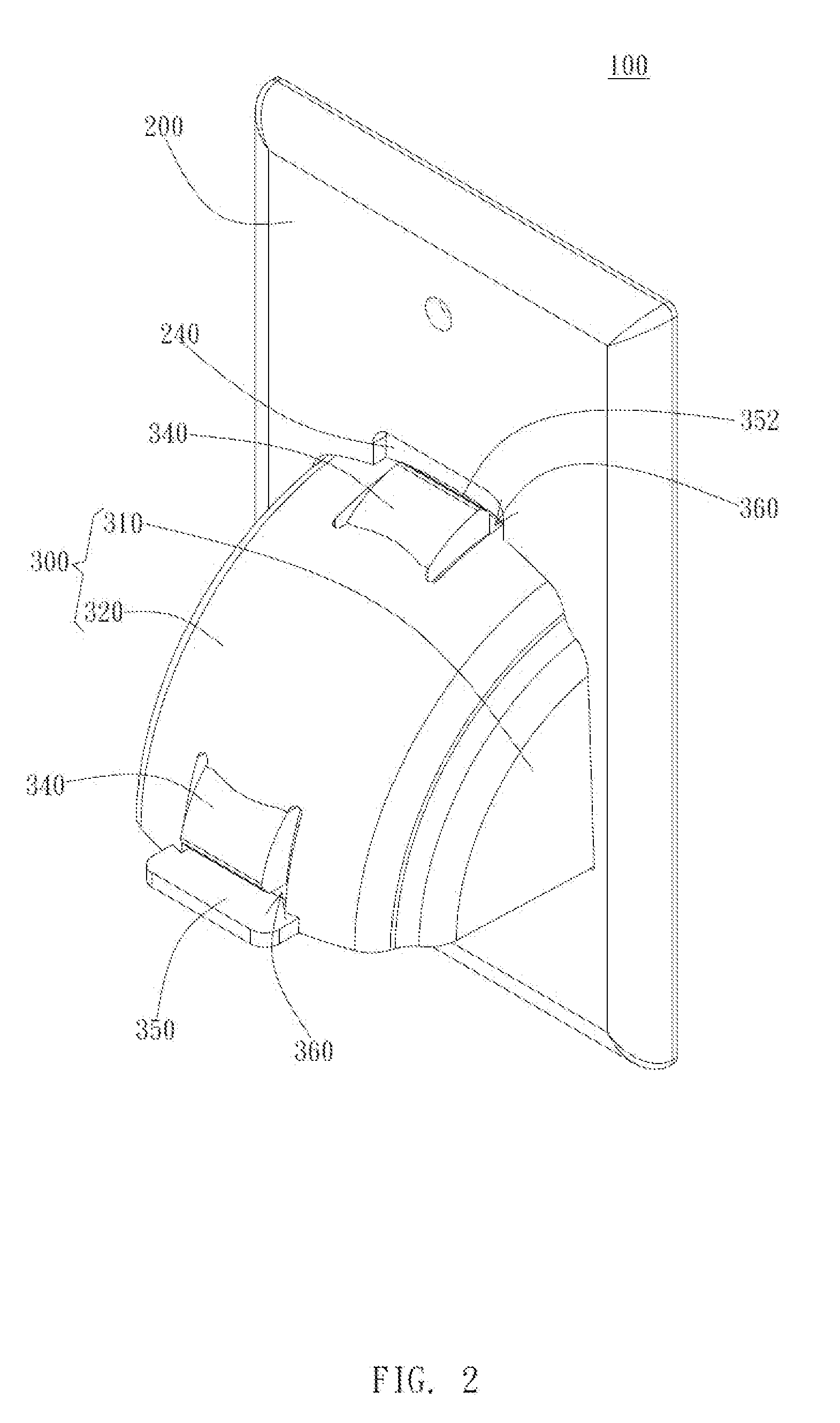
[0022]The present invention provides a mounting faceplate structure for guiding and managing a plurality of cables to meet different construction needs. The mounting faceplate described herein is preferably mounted on the wall as a wall-mount faceplate and has an opening corresponding to the hole in the wall to allow transmission lines to go therethrough. However, in other embodiments, the mounting faceplate can have more than one opening accompanied with more than one nose cover to allow transmission lines to go therethrough, respectively. The structure and operation of the present invention will be described in detail with reference to the accompanied figures.

[0023]As the FIG. 2 shows, a mounting faceplate 100 is provided to allow a plurality of cables / transmission lines to go therethrough. The mounting faceplate 100 includes a faceplate body 200 and a nose cover 300. Also referring to FIG. 3A, the faceplate body 200 has an opening 210 near a center portion thereof. The cross-sect...


PUM


Abstract

A multi-directional mounting faceplate for managing a plurality of cables is provided. The mounting faceplate includes a faceplate body and a nose cover, wherein the faceplate body has an opening disposed about the center of the faceplate body. The cross-sectional shape of the nose cover is similar to the shape of the opening. The nose cover has two side plates and a linking plate which is connected between the two side plates, such that the nose cover can be rotatably connected to the faceplate body to change the open direction of the mounting faceplate.

Description

BACKGROUND OF THE INVENTION[0001]1. Field of the Invention[0002]The present invention relates to a mounting faceplate for managing a plurality of cables and particularly relates to a wall-mount faceplate with a rotatable nose cover.[0003]2. Description of the Prior Art[0004]Generally, the transmission lines of audio and video devices such as audio system, television, computer, and home theater are connected to the system line of the building through wall-mount faceplates corresponding to holes in the wall.[0005]FIG. 1 is a perspective view of a traditional wall-mount faceplate. The conventional wall-mount faceplate 10 includes a faceplate body 1 and a rectangular cover 2. The faceplate body 1 has an opening 3 close to one side of the faceplate body 1. The size of the opening 3 is almost a half of the faceplate body 1. The shape of the opening 3 is similar to the shape of the open space 4 of the rectangular cover 2, and the opening 3 communicates with the open space 4 of the rectangu...

Claims


Application Information

Patent Timeline
IPC IPC(8): H05K5/03
CPCH05K5/03H02G3/081H02G3/14
Inventor WANG, CHU-LI
Owner EMCOM TECH
Why Eureka
Try Eureka