Vulcanised power umbilical

a technology of umbilical cord and umbilical sleeve, which is applied in the direction of cables, insulated conductors, conductors, etc., can solve the problems of zeta-kinking of single strands of power cables without this system, and achieve the effect of avoiding sagging, lowering the clinging against the filler material, and avoiding sagging

Active Publication Date: 2014-05-13
AKER SOLUTIONS AS
View PDF22 Cites 4 Cited by
  • Summary
  • Abstract
  • Description
  • Claims
  • Application Information

AI Technical Summary

Benefits of technology

[0034]It is to be understood that if the power cable extends freely all the way within said void, the copper conductor itself tends to creep an increment each time the temperature changes, for example when the conductor supplies power and not. This can be explained in the following way. The high power cable is laying as a spiraled string, or in a helix, within the longitudinal voids formed in the filler material. The cable will behave as a twining plant does to cling to something in order to avoid sagging down. As known, if the conductor is made of copper it has a substantial weight which makes it to tend to sag down when such a string extends substantially vertical over several thousands meters. However, the helix will contribute to that the twining plant effect will arise which makes it cling to the filler material and sits stable in a frictional way to the filler material as long as the temperature is stable.
[0035]When the power is switched on, heat is developed within the conductor and the conductor expands. In such lengths as are discussed here, this longitudinal expansion will be substantial. The longitudinal expansion makes the twining plant effect above to decrease and the cling against the filler material is lowered. This, however, makes no problem in first occurrence. When the power is switched off the conductor is getting colder and contracts again. However, it will cling again when contracted, but firstly in that end having longest expansion. Thus the creeping effect arises.

Problems solved by technology

The typical error mode for power cables without this system is kinking (Zeta-kinking) of single strands of the cable due to compression loads and transformations in material properties, such as strain-hardening for example.

Method used


Image

  • Vulcanised power umbilical
  • Vulcanised power umbilical
  • Vulcanised power umbilical

Examples


Embodiment Construction

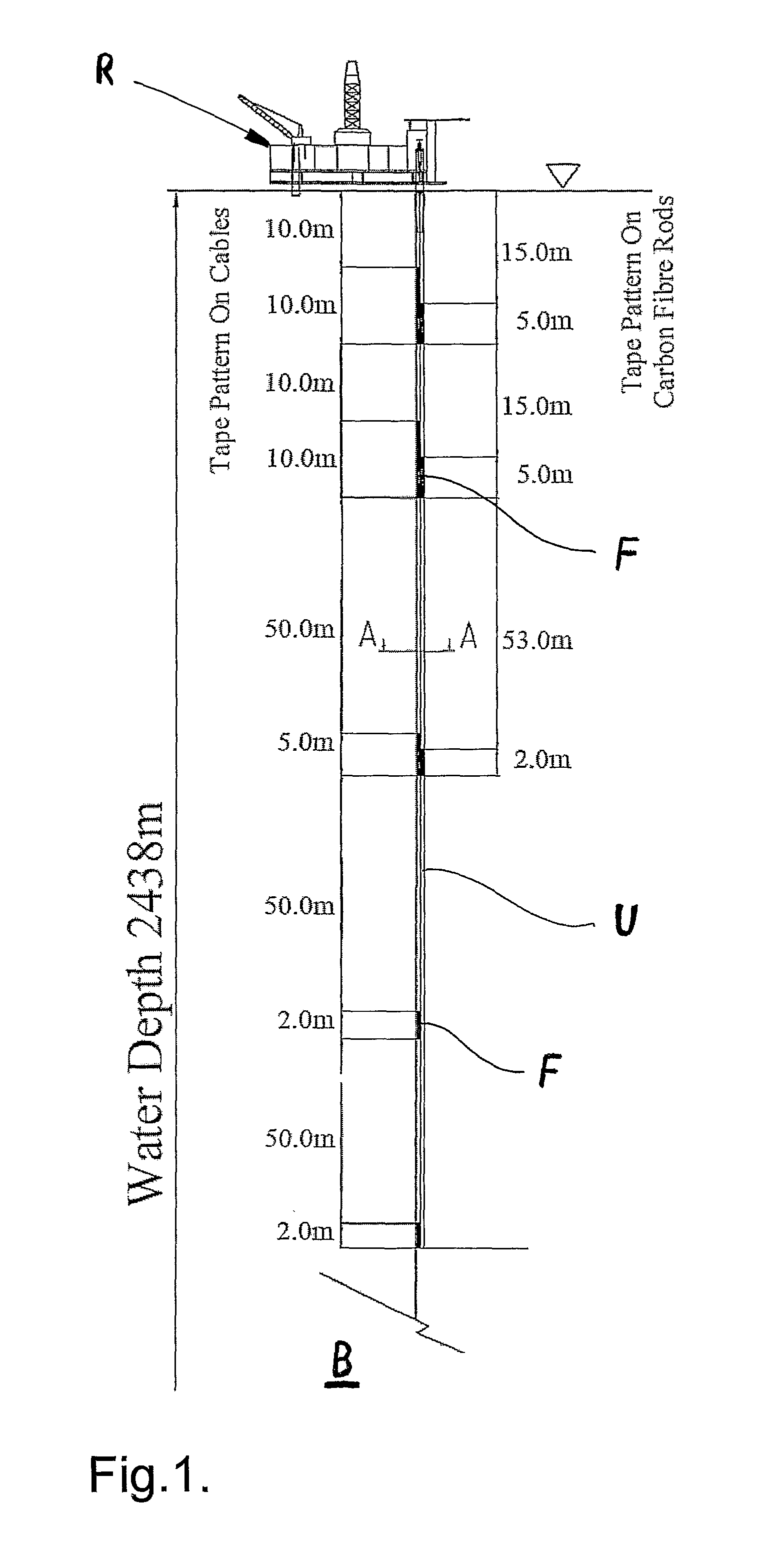
[0046]With reference to FIG. 1, a structure R floating on the sea surface is firstly shown. The structure, or the rig, do not make any part of the invention, but is shown in order to illustrate a possible usage of the invention.

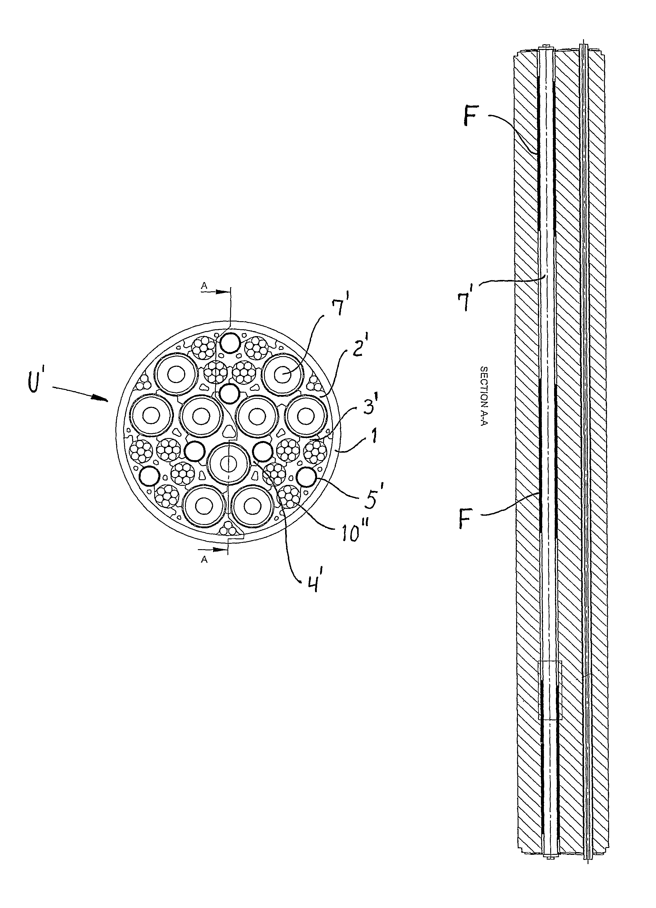
[0047]An umbilical U extends between the floating rig R and the seabed B and is schematically illustrated in the drawing. Further, where the intended frictional spots F (black fields) within the umbilical are located, are schematically marked. This is to be considered as examples without that these sizes, lengths and intervals should be considered to be limitations as lengths and dimensions concerns. These sizes can vary from one application to another. In addition, a water depth of 2483 meters is indicated as an example, just to illuminate that the umbilical can be deployed at considerable water depths.

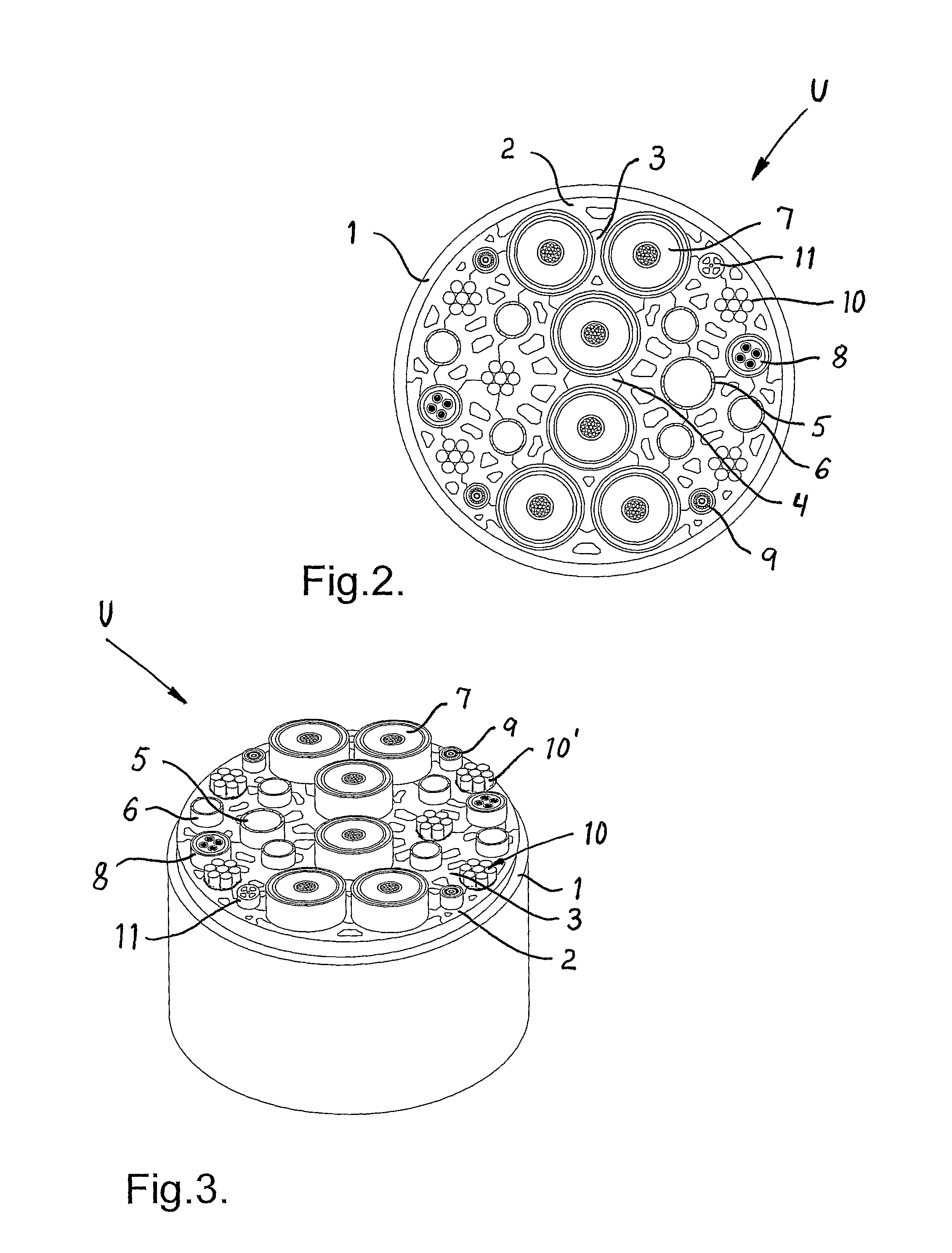
[0048]Each frictional spot, or more correctly frictional length, is in an actual embodiment realized as a vulcanisation of rubber between inner components wit...


PUM

PropertyMeasurementUnit
water depthsaaaaaaaaaa
depthsaaaaaaaaaa
anglesaaaaaaaaaa

Abstract

A power umbilical, a DEH power cable or general umbilical, including a plurality of high power cables for transfer of large amounts of electric energy, filler material in the form of stiff elongate plastic elements located at least partially around and between the high power cables, which together are collectively gathered in a spiraled bundle by means of a laying and closing operation, and a protective sheath that encapsulates the high power cables and the filler material is shown. The high power cables are at intervals in the longitudinal direction of the cables, provided with frictional material which cooperate with the filler material for frictional engagement with and load transfer between each other.

Description

CROSS-REFERENCES TO RELATED APPLICATIONS[0001]This applicant is the national stage entry of PCT / NO10 / 00437, filed Nov. 29, 2010.BACKGROUND OF THE INVENTION[0002]1) Field of the Invention[0003]The present invention relates to a power umbilical, a DEH power cable or general umbilical, including a plurality of high power cables for transfer of large amounts of electric energy, filler material in the form of stiff elongate plastic elements located at least partially around and between the high power cables and which together are collectively gathered in a spiraled bundle by means of a laying and closing operation, and a protective sheath that encapsulates the high power cables and the filler material.[0004]Thus the present invention can be used on at least three main types of umbilicals / power cables; primarily on that we call a power umbilical of the nature described in WO 2005 / 124213; on a DEH cable (Direct Electric Heating) of the type described in PCT / NO2010 / 000395 and on a more trad...

Claims


Application Information

Patent Timeline
Patent Type & Authority Patents(United States)
IPC IPC(8): H01B7/00
CPCH01B7/045F16L53/007F16L53/37
Inventor FIGENSCHOU, ARILD
Owner AKER SOLUTIONS AS
Why Eureka
Try Eureka