
Mandrel and method for manufacturing composite structures

a composite structure and mandrel technology, applied in the direction of lamination, lamination apparatus, chemical equipment and processes, etc., can solve the problems of increasing the time and cost of manufacturing process, increasing the cost of manufacturing, and difficulty in cleaning grit strips, so as to reduce the cost of mandrel, reduce the relative size of the mandrel, and reduce the thermal mass

Active Publication Date: 2005-03-10
THE BOEING CO
View PDF13 Cites 31 Cited by
  • Summary
  • Abstract
  • Description
  • Claims
  • Application Information

AI Technical Summary

Benefits of technology

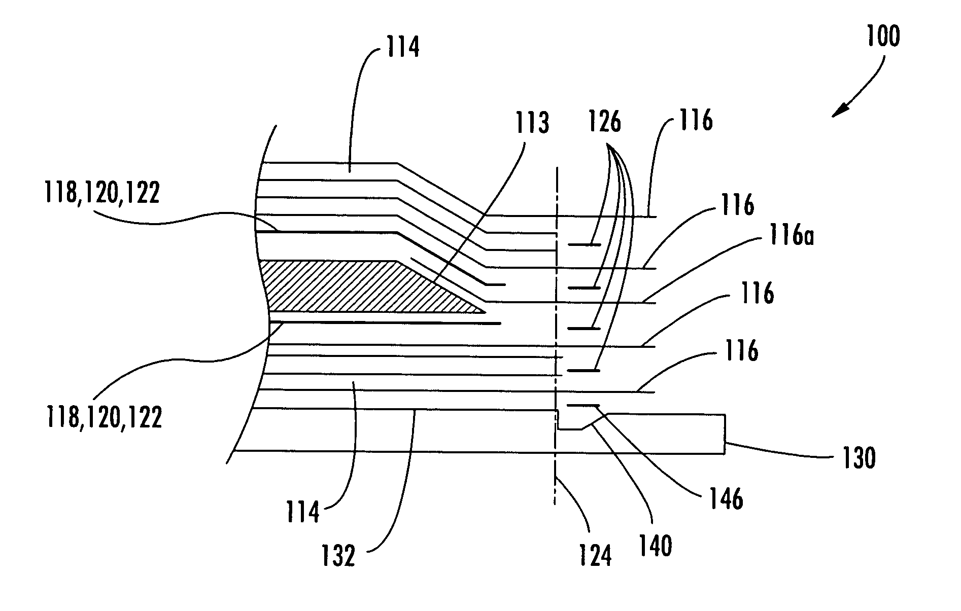
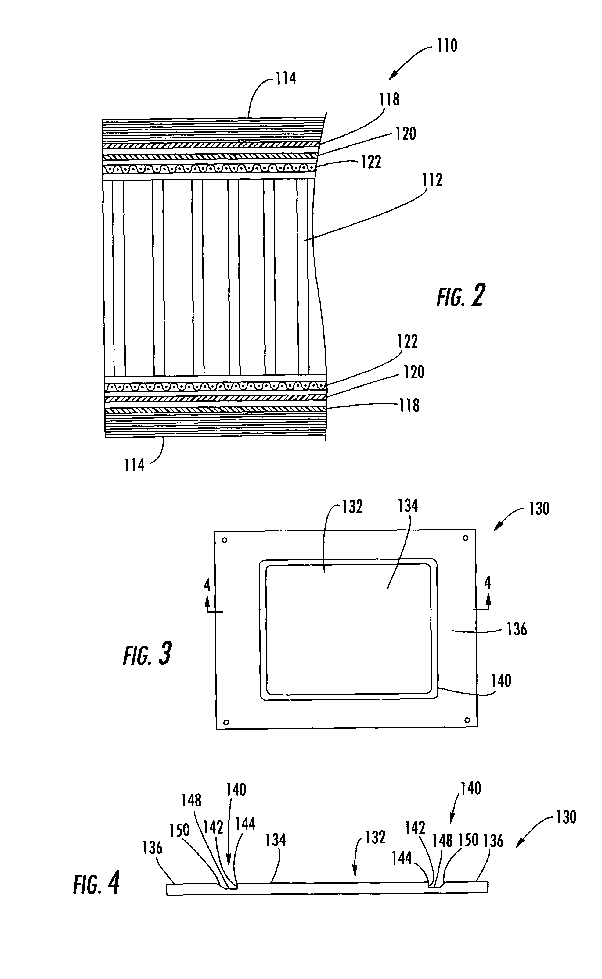
[0011] The present invention provides a mandrel and a method for retaining composite structures, such as composite honeycomb structures, during manufacture. The mandrel defines a layup surface with a grip feature, such as a groove or step, that is configured to engage the composite structure during manufacture and retain the structure in a predetermined configuration. Each of the plies of the composite structure can be secured to the mandrel proximate to the grip feature such that the mandrel need not be significantly larger than the composite structure. Thus, mandrels according to the present invention can be smaller than conventional devices for forming a composite structure of a given size. The smaller relative size of the mandrel of the present invention can reduce the cost of the mandrel. Further, the smaller size of the mandrel can have a relatively lesser thermal mass, thereby saving energy and time during cure cycles.
[0013] According to one method of the present invention, a mandrel defining a layup surface for receiving the composite structure is provided. A composite preform is assembled on the layup surface with at least one resinous laminate and at least two tiedown plies. At least one of the tiedown plies is adhered to the mandrel with the film adhesive, which is applied at the grip feature so that the tiedown ply is engaged by the grip feature and the grip feature retains the composite structure in a predetermined configuration.
[0014] For example, the laminate can include a bismaleimide (BMI) matrix resin. A barrier film of a bondable grade polyimide can also be provided adjacent the laminate, with an adhesive between the barrier film and a honeycomb core of the preform. Further, a film adhesive layer can be provided between the barrier film and the laminate, and / or a supporting scrim can be provided between the barrier film adhesive and the core to prevent sagging of the barrier film into the core cells. One or more of the tiedown plies can be placed between the adhesive and core so that the tiedown ply is in contact with the core.

Problems solved by technology

One problem encountered during the manufacture of composite structures relates to the flow of resin from the laminate skin to the core of the structure.
However, the use of the tape adds to the time and cost of the manufacturing process.
However, the grit strips also add to the manufacturing cost.
Further, the grit strips can be difficult to clean after use, requiring additional time for cleaning or replacement.

Method used


Image

  • Mandrel and method for manufacturing composite structures
  • Mandrel and method for manufacturing composite structures
  • Mandrel and method for manufacturing composite structures

Examples


Embodiment Construction

[0024] The present invention now will be described more fully hereinafter with reference to the accompanying drawings, in which some, but not all embodiments of the invention are shown. Indeed, this invention may be embodied in many different forms and should not be construed as limited to the embodiments set forth herein; rather, these embodiments are provided so that this disclosure will satisfy applicable legal requirements. Like numbers refer to like elements throughout.

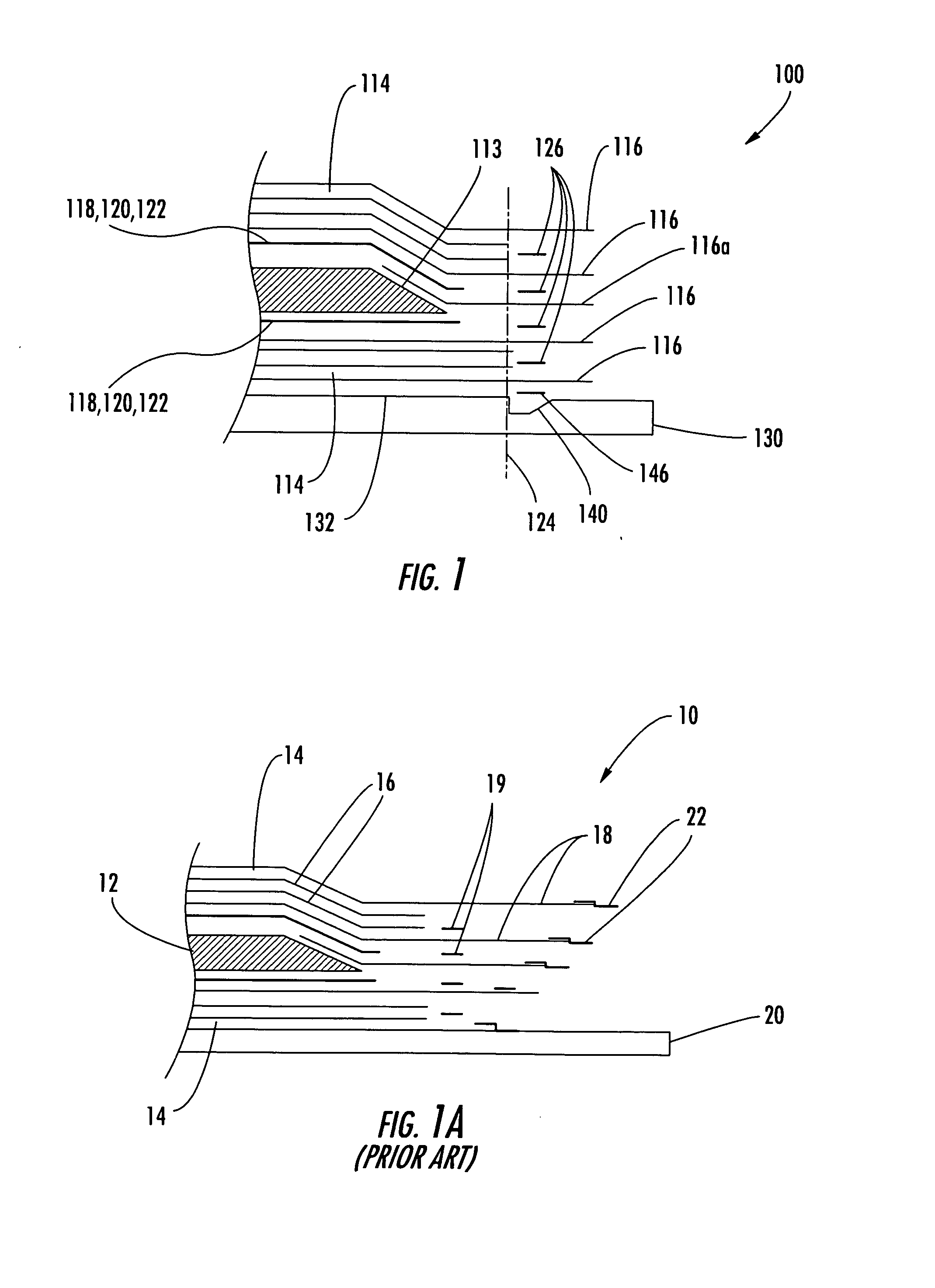
[0025]FIG. 1A illustrates a composite structure 10 during a conventional manufacture process known in the art. As shown, the structure 10 is formed of a core 12 that is sandwiched between laminar skins 14 disposed on a planar mandrel 20. The laminar skins 14 are formed of a plurality of layers of plies 16, 18, with some of the plies, referred to as tiedown plies 18, extending outward from the structure 10. The plies 16, 18 are resin-impregnated laminar sheets. For purposes of illustrative clarity, the thickness ...


PUM

PropertyMeasurementUnit
depthaaaaaaaaaa
depthaaaaaaaaaa
thickaaaaaaaaaa

Abstract

An apparatus and method for retaining composite structures, such as composite honeycomb structures, during manufacture are provided. The composite structure is cured on a mandrel that defines a layup surface with a grip feature. The grip feature is configured to engage the composite structure during manufacture and retain the structure in a predetermined configuration. A film adhesive can be provided between the grip feature and a tiedown ply that extends from the composite structure.

Description

FEDERALLY SPONSORED RESEARCH OR DEVELOPMENT [0001] This invention was made with Government support under contract number N00140-95-2-J044 awarded by the U.S. Navy. The government has certain rights in this invention.BACKGROUND OF THE INVENTION [0002] 1) Field of the Invention [0003] The present invention relates to the manufacture of composite structures and, in particular, to the securing of composite structures such as honeycomb sandwich structures to a mandrel to prevent distortion during manufacture. [0004] 2) Description of Related Art [0005] Composite structures are manufactured for use in a variety of structural applications where the structures provide high stiffness-to-weight and strength-to-weight ratios. For example, a honeycomb core sandwich panel has composite laminate skins that are co-cured with adhesives to opposite sides of a lightweight honeycomb core that can be formed of paper, metal, and the like. Such structures are described in U.S. Pat. Nos. 5,284,702; 4,622,...

Claims


Application Information

Patent Timeline
Patent Type & Authority Applications(United States)
IPC IPC(8): B29C70/34B29C70/54B32B37/14
CPCB29C70/342B32B37/146B29C70/543
Inventor ERICKSON, DAVE G.GEORGE, PANAGIOTIS E.MORTENSEN, RYAN C.SMITH, STUART A.
Owner THE BOEING CO
Learn More