Ignition device for exothermic welding, mold for exothermic welding for the ignition device, and apparatus for exothermic welding comprising such a mold and such an ignition device

a technology of exothermic welding and ignition device, which is applied in the direction of combustion ignition, soldering auxiliary devices, combustion process, etc., can solve the problems of affecting the stability of the plate, affecting the welding effect, so as to reduce the risk, prevent or reduce the effect of risk

Active Publication Date: 2015-02-12
APLICACIONES TECHCAS
View PDF2 Cites 5 Cited by
  • Summary
  • Abstract
  • Description
  • Claims
  • Application Information

AI Technical Summary

Benefits of technology

[0049]To prevent or at least reduce risks for the person who is welding, the electronic ignition device preferably comprises at least one warning alarm, selected from light alarms, sound alarms and combinations thereof, connected to the microcontroller, which is activated when the power supply to the power output is initiated and remains activated at least until the exothermic reaction of the first welding material has ended. The microcontroller can be programmed to keep the warning alarm activated for a safe time period after the end of the first exothermic reaction and, optionally, also after the end of the second exothermic reaction, corresponding to a cooling time that the mold requires until being cooled to a safe temperature that does not involve the risk of injury for a person that gets close to the weld mold. The microcontroller can alternatively or complimentarily be programmed to keep the warning alarm activated until a temperature sensor detects a safe mold temperature after the end of the exothermic reactions that does not involve the risk of injury for a person that gets close to the mold.
[0050]As can be inferred from above, the present invention overcomes the drawbacks of the systems for exothermic welding processes in an effective, safe and simple manner.

Problems solved by technology

Therefore, the support plate and the poured welding material powder can present a problem depending on the use conditions or when the mold is deteriorated and the hopper shoot widens.
This disrupts plate stability and the welding material passes as powder into the welding chamber, where its reaction will produce slag that does not separate from the molten copper.
Furthermore, the suitable arrangement of the initiating material and of the welding material in the crucible hopper or weld mold hopper requires relatively extensive preparation time.
The problems in using and transporting the initiating reactant also make the elimination thereof advisable since environmental conditions (air, temperature, humidity) affect the ease of ignition thereof, whereas due to its chemical characteristics, transport thereof is restricted in some cases and according to importing countries.
Containers of the type described above and the corresponding ignition systems can cause unwanted combustions and residues in the slag or even in the final weld and considerably increase the volume of the product since the container has the same shape as the hopper.
The slag that is generated also increases because if the container is not consumed it becomes a residue, and if it is consumed it becomes part of the weld with the composition problems of the molten material which should make the initial mixture change, entailing an additional problem.
In turn, if the container is not shaken, over time the heavier components of the mixture could accumulate on the bottom portion of the container, which leads to variations in the partial composition of the welding material affecting the main reaction.
This presents an occupational hazard inherent to the welding process itself, so the remote detonation or ignition of said process greatly reduces the risks of burns in operators and technicians doing the welding.

Method used


Image

  • Ignition device for exothermic welding, mold for exothermic welding for the ignition device, and apparatus for exothermic welding comprising such a mold and such an ignition device
  • Ignition device for exothermic welding, mold for exothermic welding for the ignition device, and apparatus for exothermic welding comprising such a mold and such an ignition device
  • Ignition device for exothermic welding, mold for exothermic welding for the ignition device, and apparatus for exothermic welding comprising such a mold and such an ignition device

Examples


Embodiment Construction

[0019]The object of the present invention is to overcome the drawbacks of the state of the art described above by means of an ignition device for exothermic welding, a mold for exothermic welding for the ignition device, and an apparatus for exothermic welding comprising the mold and the device.

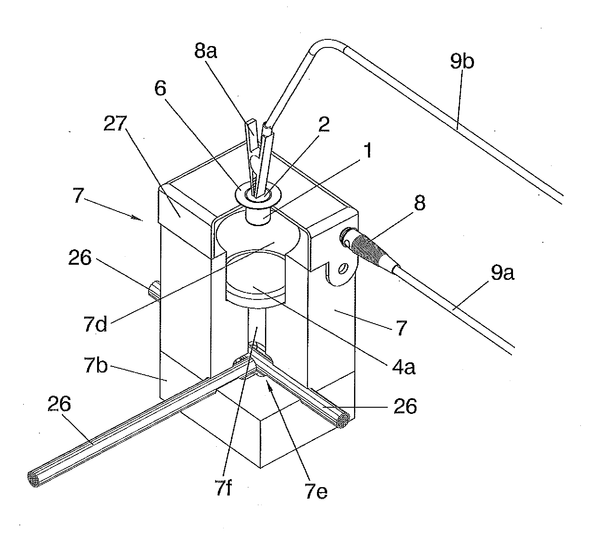
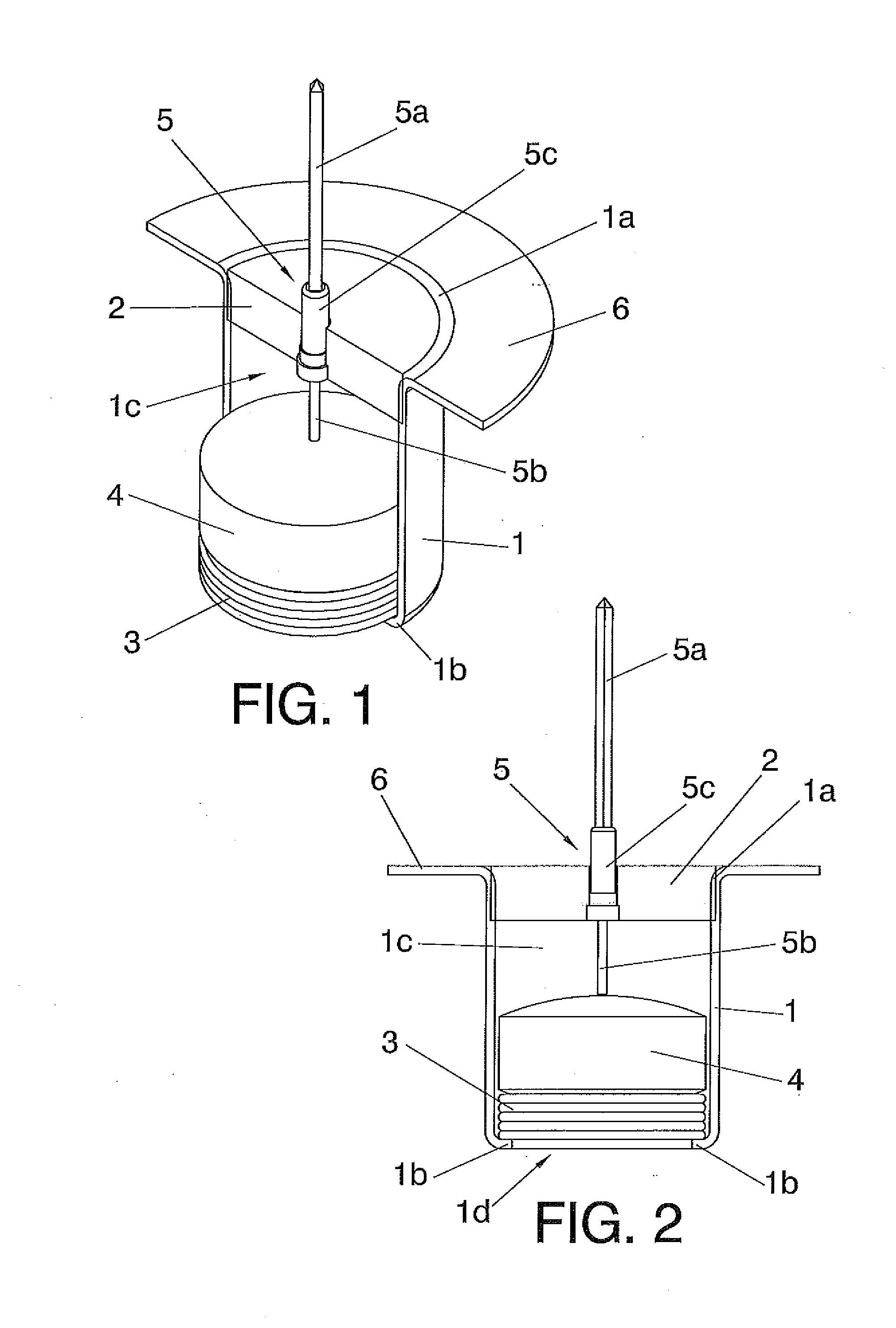
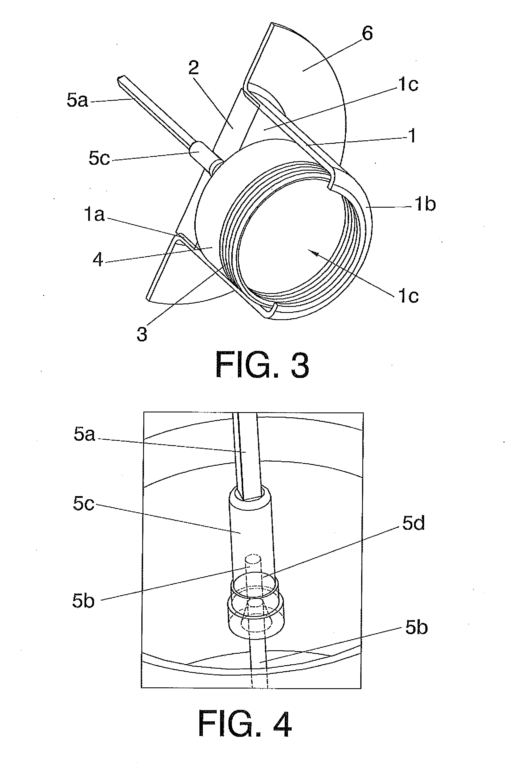
[0020]The ignition device for exothermic welding comprises a metal container at least partially housable in a weld mold, the metal container comprising a top base closed by a cap, a bottom base and an inner chamber for housing a first welding material having an ignition temperature, and ignition means for initiating and triggering a first exothermic reaction in said first welding material intended for subsequently triggering a second exothermic reaction in a second welding material, in which

[0021]the metal container is an electrically conductive metal bushing contemplated as being connectable to a first pole of a power output of a voltage generator;

[0022]the cap of the metal bushing is made o...


PUM

PropertyMeasurementUnit
apparent densityaaaaaaaaaa
grain size distributionaaaaaaaaaa

Abstract

The present invention relates to an ignition device for exothermic welding comprising an electrically conductive metal bushing (1) that can house a pellet of a first welding material (4) in electrical contact with the inner wall of an inner chamber (1c) of the bushing (1), provided with an electrically insulating cap (2) and a bottom base (1b) with an opening (1d) through which the first welding material (4) falls in an incandescent state onto a second welding material (4a) arranged in a weld mold (7) when an exothermic reaction has been triggered in the first welding material (4); an electrode (5) that goes through the cap (2) of the metal bushing (1) and comprises a top contact (5a) connectable to a power output (24) of a voltage generator and a bottom contact in the form of a filament (5b) that can be in electrical contact with the pellet of the first welding material (4), the filament (5b) being made of a material having a melting temperature greater than the ignition temperature of the welding material (4); as well as a contact-assuring element (3) which is guided into the inner chamber (1c) between the bottom base (1b) and the pellet of the first welding material (4).

Description

TECHNICAL FIELD OF THE INVENTION[0001]The present invention is comprised in the technical field of systems used for exothermic welding used, for example, for welding conductors such as strips and cables, such as those used in installations for protecting against rays and ground connections.BACKGROUND OF THE INVENTION[0002]Exothermic welding, particularly copper-based aluminothermic welding, is based on reducing copper oxide by metallic aluminum. The reaction is highly exothermic, releasing a large amount of heat, being able to reach temperatures greater than 1000° C. These conditions allow melting the materials to be welded, being joined together by the result of the heat generated by the exothermic reaction.[0003]Although the reaction is chemically aluminothermic, it is known as exothermic welding, conventionally being produced by means of an initiating reactant providing enough energy to activate the process, which takes place rapidly and safely inside a mold, preferably a graphit...

Claims


Application Information

Patent Timeline
Patent Type & Authority Applications(United States)
IPC IPC(8): B23K23/00B23K37/00B23K37/04B23K37/06
CPCB23K23/00B23K37/04B23K37/00B23K37/06F42B3/10
Inventor POMAR GARCIA, CARLOSPOMAR PEDREDO, VERONICA
Owner APLICACIONES TECHCAS
Why Eureka
Try Eureka