Surface light source device and liquid crystal display device

a surface light source and liquid crystal display technology, applied in the direction of planar/plate-like light guides, lighting and heating apparatuses, instruments, etc., can solve the problems of light leakage from warped portions light etc., to achieve uniform luminance of light emission of surface light source devices, reduce leakage to the outside of light guide plates, and low refractive index layer

Active Publication Date: 2011-08-04
TOHOKU DENSHI CO LTD
View PDF3 Cites 24 Cited by
  • Summary
  • Abstract
  • Description
  • Claims
  • Application Information

AI Technical Summary

Benefits of technology

[0027]In this embodiment, the inclined surface is formed at the edge of the light introducing portion so that the thickness is thin on a light introducing portion side. Therefore, by reflecting light entering the inside of the light introducing portion off the inclined surface, the directivity spread in the thickness direction of the light guide plate can be narrowed, and the light with the narrowed directivity spread can be fed to the light guide plate body. With this, inside the light guide plate body, light not reflected off the light emitting means and leaking to the outside of the light guide plate body can be reduced. In particular, even when a layer having a refractive index lower than the refractive index of the light guide plate body is provided on the light emission surface of the light guide plate body, light not reflected off the light emitting means and leaking from the interface between the light guide plate body and the low refractive index layer can be reduced. As a result, light can be guided to a position away from the point source of light, and luminance of light emission of the surface light source device can be made uniform.
[0028]In still another embodiment of the first or second surface light source device of one or more embodiments of the present invention, a surface of the light guide plate on a light emission surface side and/or a surface thereof opposite thereto is covered so as to be in intimate contact with a low refractive index layer having a refractive index smaller than a refractive index of the light guide plate. As in this embodiment, when the surface of the light guide plate is covered with a low refractive index layer, if no directivity converting portion is provided, light of the point source of light entering the inside of the light guide plate passes thr

Problems solved by technology

However, when the thickness of the light guide plate is reduced, the light guide plate becomes slim like a sheet, and tends to be warped.
And, when the light guide plate tends to be warped, assembling a backlight is difficult, and light can be leaked from a warped portion of the light guide plate.
Therefore, lig

Method used


Image

  • Surface light source device and liquid crystal display device
  • Surface light source device and liquid crystal display device
  • Surface light source device and liquid crystal display device

Examples


second modification example of first embodiment

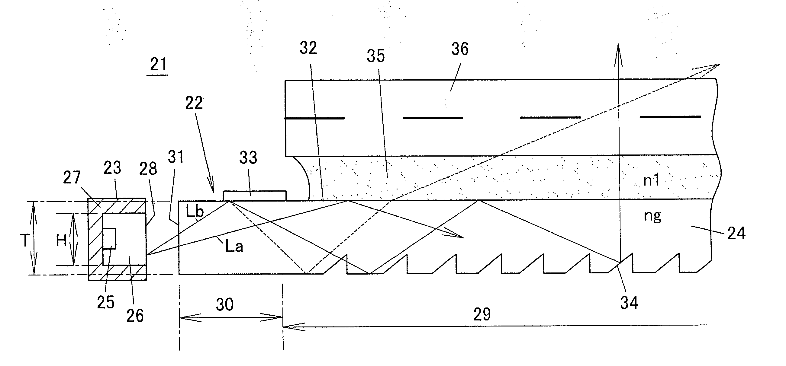
[0170]FIG. 30 is a perspective view of a light guide plate 24 according to a second modification example, and FIG. 31 is a partially-sectional schematic view thereof. In this light guide plate 24, a directivity converting portion 33 is formed so that the surface of the light guide plate 24 is recessed, and each ridgeline 38a of arranged V-grooved directivity conversion patterns 37 is horizontal, and is in the same plane as that of the light emission surface 32. An end of a valley line 38b on a side near a point source of light 23 has a shallow depth, and an end of the valley line 38b on a side away from the point source of light 23 has a deep depth. Therefore, the V groove of the directivity converting portion 33 linearly goes deeper as going away from the point source of light 23, and the valley line 38b is also linearly tilted. Also, the inner perimeter surface and the outer perimeter surface of the directivity converting portion 33 are perpendicular surfaces with respect to a fla...

third modification example of first embodiment

[0172]FIG. 33(a) is a plan view of the shape of a directivity converting portion 33 according to a third modification example, and FIG. 33(b) is a schematic sectional view thereof passing through its ridgeline 38a. In the first embodiment, the inner perimeter edge and the outer perimeter edge of the directivity converting portion 33 are in an arc shape, and the inner perimeter surface and the outer perimeter surface of the directivity converting portion 33 are perpendicular surfaces. In the first embodiment, because the outer perimeter surface is a perpendicular surface, when light enters the outer perimeter surface of the directivity converting portion 33 at an angle of incidence smaller than the critical angle of total reflection, light may leak from the outer perimeter surface.

[0173]By contrast, in the third modification example, the inner perimeter edge of the directivity converting portion 33 is in an arc shape, but the outer perimeter edge of the directivity converting portion...

fourth modification example of first embodiment

[0176]FIG. 34(a) is a perspective view of a surface light source device 46 according to a fourth modification example, and FIG. 34(b) is a partially-enlarged perspective view thereof. In this surface light source device 46, a directivity converting portion 33 is provided in a linear band-shaped region from one side end of the surface of a light guide plate 24 to another side end. Although the directivity converting portion 33 has a bilaterally symmetrical shape, each directivity conversion pattern 37 forming the directivity converting portion 33 is radially formed centering on a point source of light 23 or one point near the point source of light 23. Therefore, as depicted in FIGS. 35(a), 35(b), and 35(c), the directivity conversion pattern 37 has a different shape depending on the position of the directivity converting portion 33. That is, FIG. 35(a) depicts a part of the shape of the directivity conversion pattern 37 in a portion D1 in FIG. 34, FIG. 35(b) depicts a part of the sha...


PUM


Abstract

A surface light source device includes a point source of light and a light guide plate causing light from the point source of light introduced from a light incident end face and emitted from a light emission surface to outside. The light guide plate is formed of a light introducing portion provided at an end of a light guide plate body. The point source of light is placed facing the light incident end face positioned at an end face of the light introducing portion. Along a region of the light introducing portion adjacent to the light guide plate body, a directivity converting portion is provided. The directivity converting portion is configured by arranging V-grooved directivity conversion patterns in an arc shape. A region of the light introducing portion has a thickness equal to that of the light guide plate body and has a surface positioned in the same plane.

Description

TECHNICAL FIELD[0001]The one or more embodiments of the present invention relate to surface light source devices and liquid crystal display devices and, more specifically, to a surface light source device with a light guide plate that can be slimmed down and a liquid crystal display device using the surface light source device.BACKGROUND ART[0002]To slim down a backlight used in a liquid crystal display device or the like, it is required to omit an additional sheet, such as a light diffusion sheet, and also reduce the thickness of a light guide plate itself.[0003]However, when the thickness of the light guide plate is reduced, the light guide plate becomes slim like a sheet, and tends to be warped. And, when the light guide plate tends to be warped, assembling a backlight is difficult, and light can be leaked from a warped portion of the light guide plate. Therefore, as a method of preventing warping of the slimmed light guide plate, there is a method of affixing the light guide pla...

Claims


Application Information

Patent Timeline
IPC IPC(8): G02F1/13357F21V8/00
CPCG02B6/0016G02B6/0028G02F1/133615G02B6/0068G02B6/0038
Inventor SHINOHARA, MASAYUKITANOUE, YASUHIROISHIKAWA, TAKAKOUENO, YOSHIHIRO
Owner TOHOKU DENSHI CO LTD
Why Eureka
Try Eureka