
Enclosure and method for temperature-sensitive components

a technology of enclosure and temperature-sensitive components, applied in the field of enclosure and method, can solve the problems of short duration, failure of temperature measurement devices or other electronic components or elements, and limited thermocouple recording devices

Active Publication Date: 2011-08-04
ILLINOIS TOOL WORKS INC
View PDF10 Cites 8 Cited by
  • Summary
  • Abstract
  • Description
  • Claims
  • Application Information

AI Technical Summary

Benefits of technology

[0019]In yet another embodiment, a method of protecting a heat-sensitive data recording device is provided. The method comprises: placing the recording device into a protective enclosure, the protective enclosure comprising: a housing for containing the recording device; a compartment for containing a heat absorbing element; a jacket around the compartment, the jacket configured to contain a liquid; and a vent operatively connected to the jacket to allow for the release of vapors if the liquid vaporizes. The method further comprises placi

Problems solved by technology

When exposed to such temperatures, whether for an extended period of time at the lower end of the temperature range or for a shorter period of time at the higher end of the temperature range, temperature measuring devices or other electronic components or elements may fail due to the exposure.
Thermocouple recording devices are available to record profiles through a diffusion furnace but they are limited to short durations at high process temperatures (e.g., less than 3 min. at 850° C.) since the amount or thickness of protective insulation is restricted by the short vertical clearance in the furnaces.
Diffusion furnaces using a conveyor need >10 min. at ˜850° C. to produce a PN junction in a solar cell; but most thermocouple recording devices cannot survive a 10 minute exposure at such a temperature.

Method used


Image

  • Enclosure and method for temperature-sensitive components
  • Enclosure and method for temperature-sensitive components
  • Enclosure and method for temperature-sensitive components

Examples


Embodiment Construction

[0026]The following detailed description is to be read with reference to the drawings, in which like elements in different drawings have like reference numbers. The drawings, which are not necessarily to scale, depict selected embodiments and are not intended to limit the scope of the invention. Skilled artisans will recognize that the given examples have many alternatives that fall within the scope of the invention.

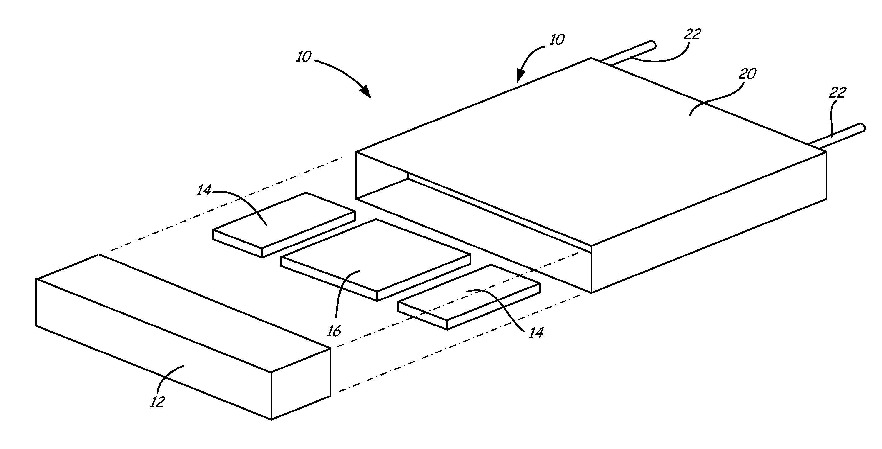
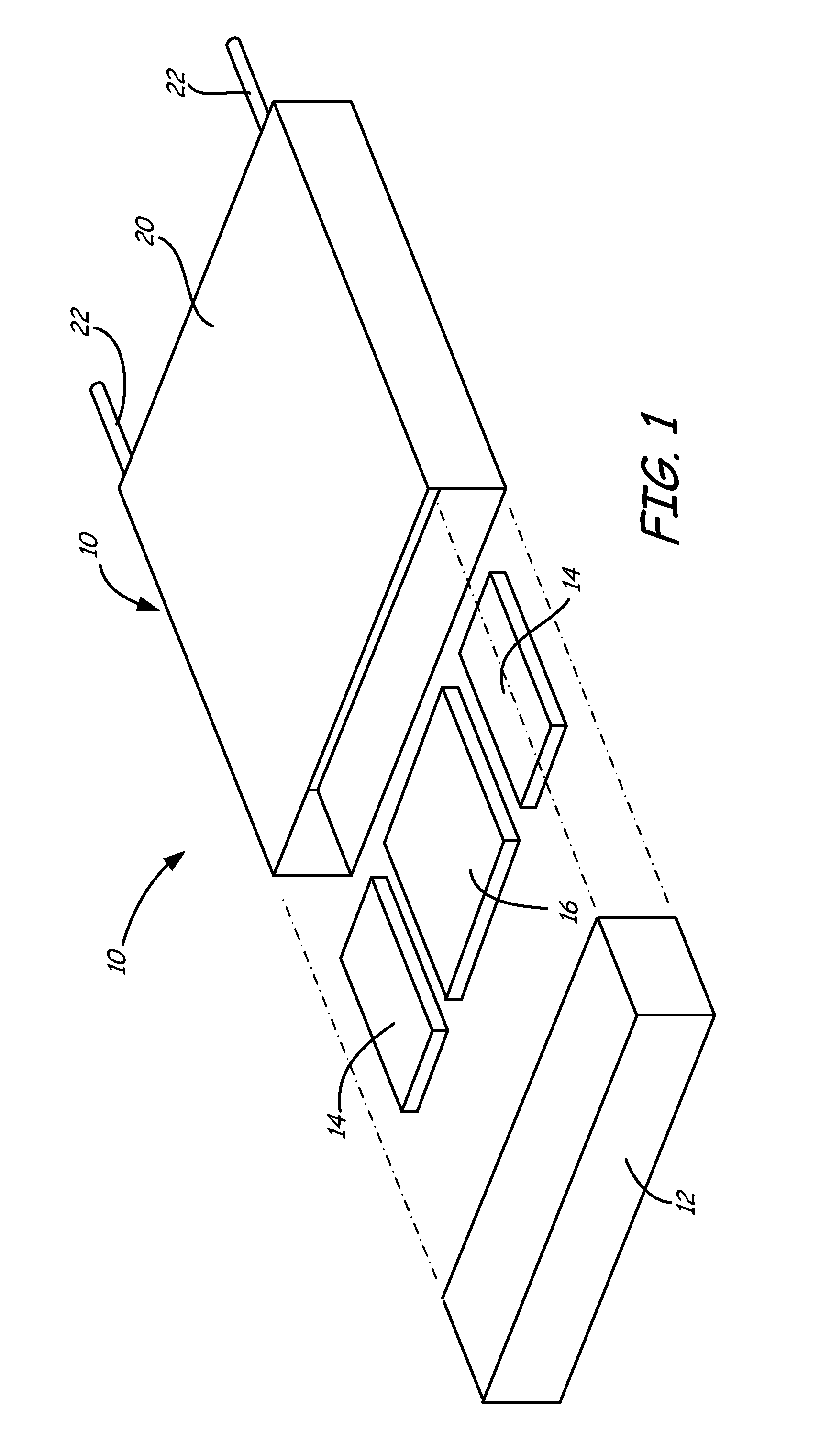
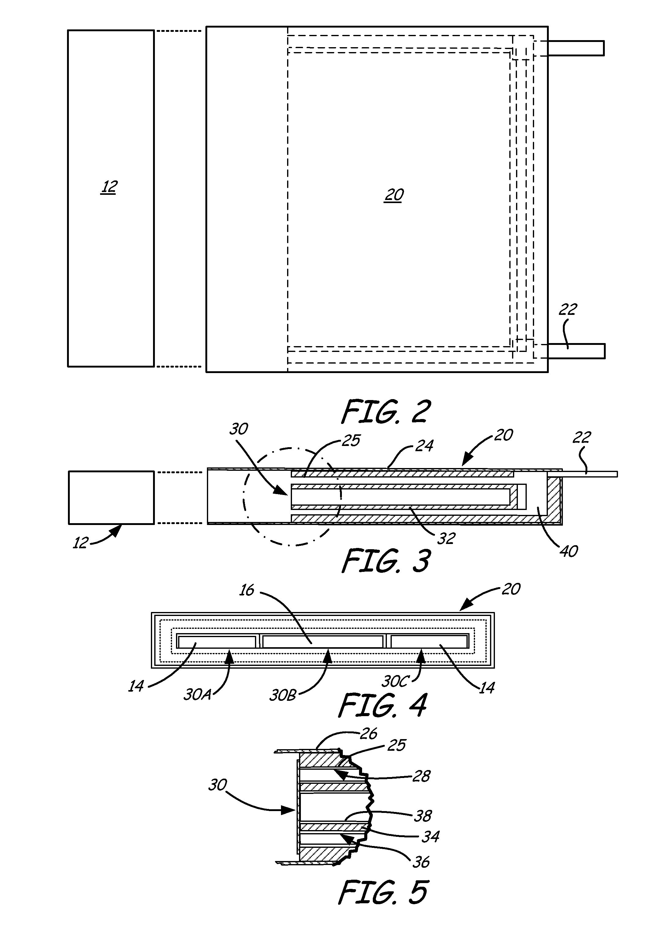
[0027]Referring to FIG. 1, a protective enclosure 10 according to an embodiment of the invention is shown in exploded view. In the embodiment of FIG. 1 and FIG. 2, enclosure 10 has an endcap 12 and a housing 20. Also shown are heat absorbing or phase change elements 14 and a device to be protected 16. Device 16 may be a temperature sensitive component. For example, device 16 may be a temperature data recording device electrically coupled to a thermocouple (not shown in FIG. 1 and FIG. 2) that is positioned outside of protective enclosure 10. Phase change elements 14 and ...


PUM

PropertyMeasurementUnit
Temperatureaaaaaaaaaa
Volumeaaaaaaaaaa
Phaseaaaaaaaaaa

Abstract

Protective enclosure and method for protecting heat sensitive, data recording devices in high temperature environments. The protective enclosure has a housing having at least one compartment for containing a heat sensitive, data recording device, e.g., a temperature recording device, and a jacket configured to contain a phase change material. The jacket may be vented and configured to at least partially surround the compartment. The housing may be sealed with an endcap. The recording device and a heat absorbing element are disposed within the same or within adjoining or adjacent sub-compartments within the enclosure. In a method, the enclosure with heat absorbing element and temperature recording device is placed within a heated environment or environment to be heated, e.g., a furnace. The recording device is connected to a thermal couple.

Description

RELATED APPLICATIONS[0001]The present application claims priority to International Application No. PCT / US2009 / 054877 filed Aug. 25, 2009, which in turn claims priority to U.S. Provisional Application No. 61 / 091,583 filed Aug. 25, 2008, the teachings of which are incorporated herein by reference.FIELD OF THE INVENTION[0002]The present invention relates to an enclosure and method. More particularly, the invention relates to an enclosure and method for protecting temperature sensitive devices exposed to high process temperature environments.BACKGROUND OF THE INVENTION[0003]A variety of ovens and furnaces are used to process workpieces or materials that require exposure to heat or heat treatment, often at specific controlled temperatures. Such workpieces or materials may include, for example, metals to be pre-heated, silicon wafers treated with dopant, materials for use in photovoltaic cells requiring conductive paste to be fused thereto, and any other workpieces or materials that requi...

Claims


Application Information

Patent Timeline
IPC IPC(8): G01K7/02F28F9/00B65B5/00
CPCG11B33/1426F27D21/00G01K1/12
Inventor MELGAARD, HANS L.
Owner ILLINOIS TOOL WORKS INC
Learn More