Vessel for interring cremated remains and associated methods

a cremated remains and vessel technology, applied in the field of cremation, can solve the problems of not meeting unable to meet the needs of the industry, drawbacks related to design and cost, etc., and achieve the effect of lowering and raising the level of difficulty

Inactive Publication Date: 2011-08-11
FORREST GEORGE G +1
View PDF15 Cites 24 Cited by
  • Summary
  • Abstract
  • Description
  • Claims
  • Application Information

AI Technical Summary

Benefits of technology

A pair of handles may be connected to the sidewalls of the outer shell and oriented to oppose one another. A pair of grooves may be formed in the bottom portion of the base and may be aligned substantially parallel with one another. Each of the pair of grooves may extend from a first end of an outer peripheral portion of the bottom portion of the base to a second end of the outer peripheral portion of the bottom portion of the base. The pair of grooves are advantageously adapted to receive ropes, for example, so that the cremated remains containment vessel may be readily raised and lowered into a burial site.

Problems solved by technology

These solutions, however, are unable to meet some of the needs of the industry because not all individuals interested in casket burials are able to afford the type and look of the casket they desire for their loved ones.
However, these solutions similarly fail to meet some of the needs of the industry and suffer from a variety of drawbacks related to design and cost.
One of the problems with the current state of the art that has been recognized is that existing urns and vaults are difficult to handle, particularly when lowering the vault into a grave during an interment, or when raising the vault from the ground during a disinterment.
Still other solutions seek to make up for cost-related deficiencies by providing financial solutions, such as payment plans or credit cards, but these solutions also fail to meet industry needs because many funeral homes have difficulty collecting payment after the interment is complete, or families are left with untold financial problems when settling funeral expenses.

Method used


Image

  • Vessel for interring cremated remains and associated methods
  • Vessel for interring cremated remains and associated methods
  • Vessel for interring cremated remains and associated methods

Examples


Embodiment Construction

The present invention will now be described fully hereinafter with reference to the accompanying drawings, in which preferred embodiments of the invention are shown. This invention may, however, be embodied in many different forms and should not be construed as limited to the embodiments set forth herein. Rather, these embodiments are provided so that this disclosure will be thorough and complete, and will fully convey the scope of the invention to those skilled in the art. Those of ordinary skill in the art will realize that the following embodiments of the present invention are only illustrative and are not intended to be limiting in any way. Other embodiments of the present invention will readily suggest themselves to such skilled persons having the benefit of this disclosure.

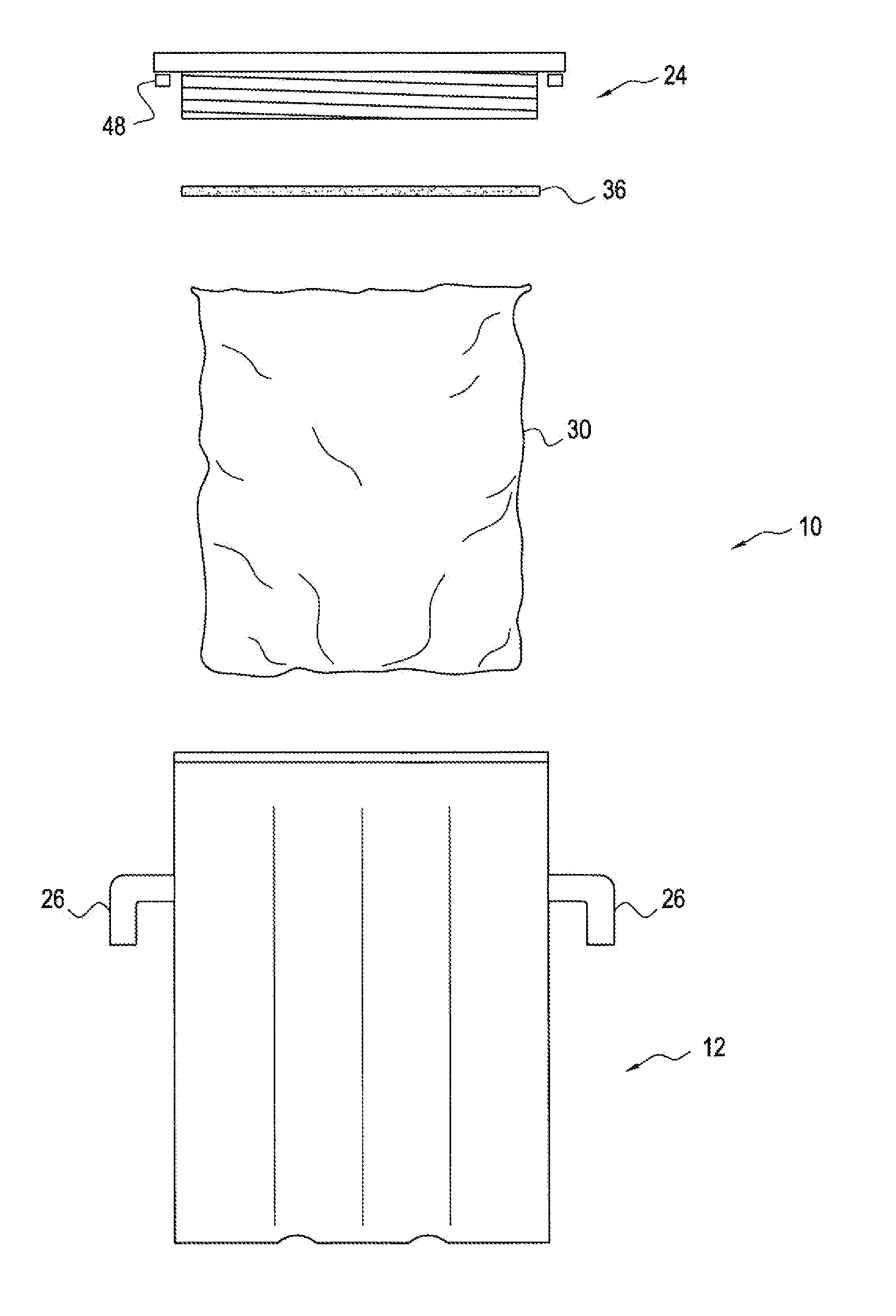
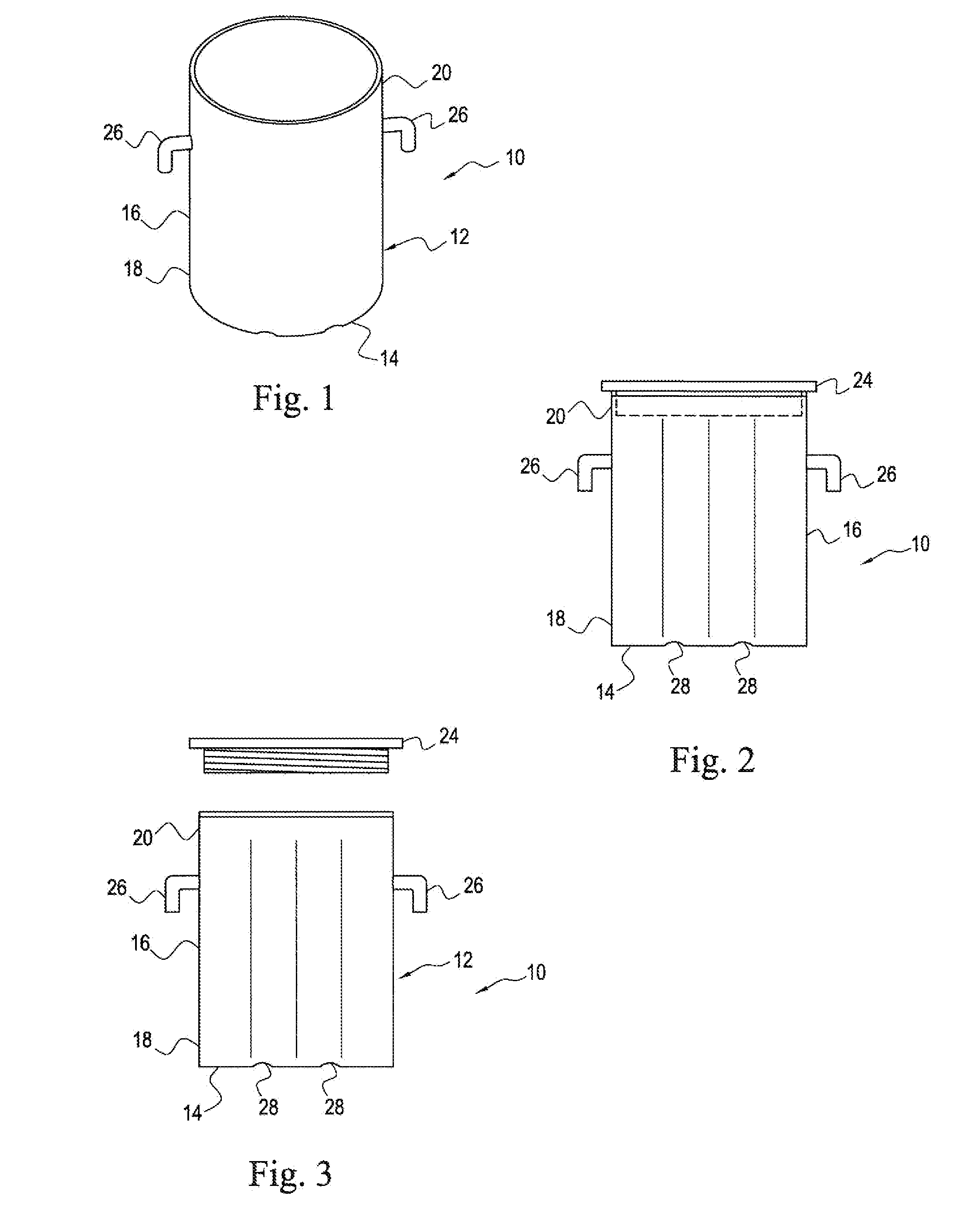
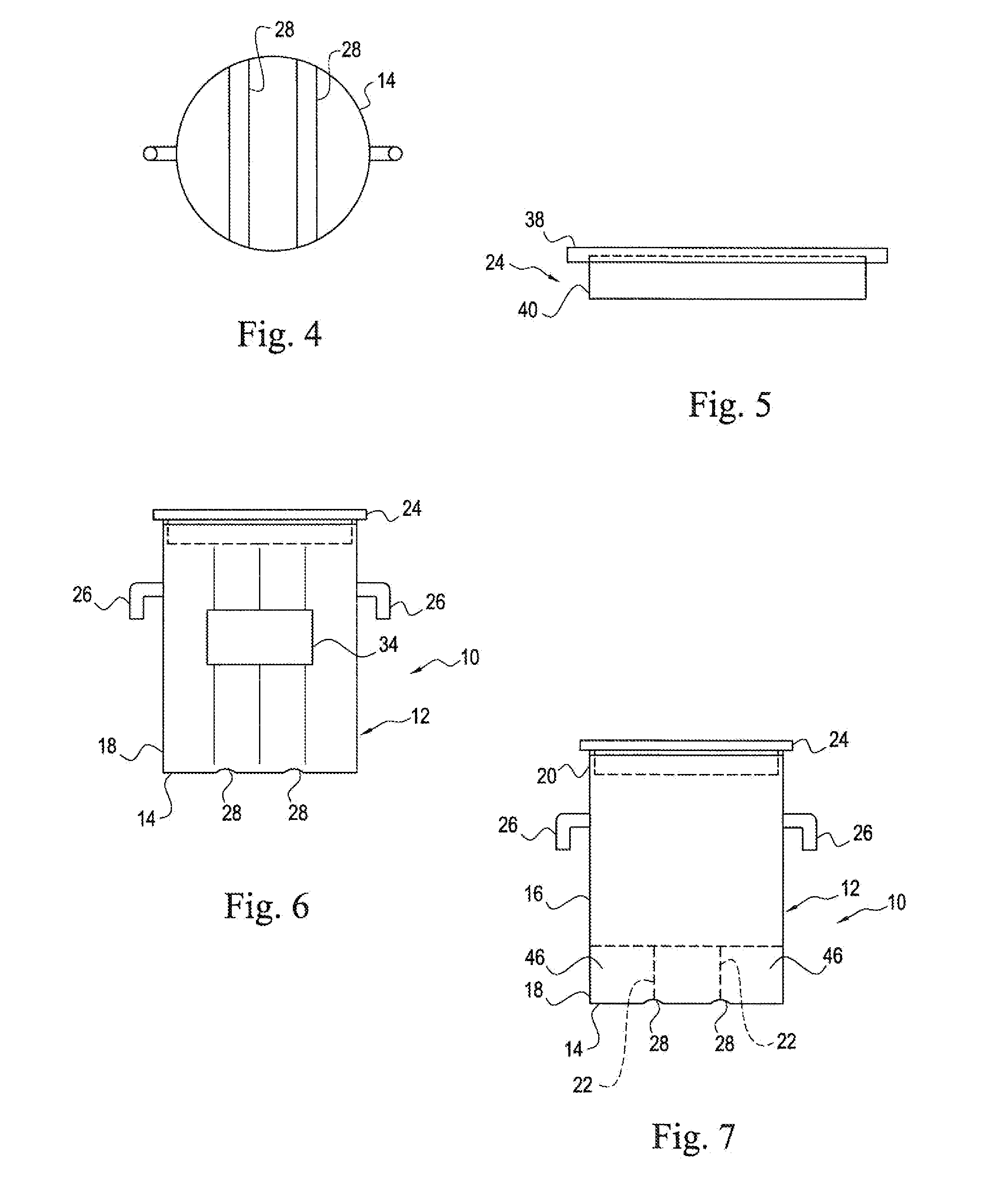
Referring now to FIGS. 1-14, a cremated remains containment vessel 10 according to the present invention is now described in greater detail. Throughout this disclosure, the cremated remains containment vesse...


PUM


Abstract

A cremated remains containment vessel may include an outer shell including a base and sidewalls extending upwardly from the base. The sidewalls may be defined by a lower portion positioned adjacent the base and an upper portion positioned opposite the base. The outer shell may also include a plurality of interior walls extending upwardly from the base, interior the sidewalls, to define a plurality of compartments. The vessel may also include a top that is removeably connected to the upper portion of the sidewalls, and a pair of handles connected to the sidewalls of the outer shell to oppose one another. The vessel may further include a pair of grooves formed in a bottom portion of the base and aligned substantially parallel with one another. The vessel may still further include a liner carried by the outer shell adjacent an inner portion of the sidewalls and the base, and a data plate carried by a bottom portion of the top. The vessel may also include a frame member carried by an outer portion of the sidewalls. Contact between the top and the outer shell may form an airtight or watertight seal.

Description

FIELD OF THE INVENTIONThe present invention relates generally to the field of cremation and, more specifically, to a vessel for preserving cremated remains, and associated methods.BACKGROUND OF THE INVENTIONCurrently there are a number of solutions for interring human remains. Some of these solutions include casket interments. These solutions, however, are unable to meet some of the needs of the industry because not all individuals interested in casket burials are able to afford the type and look of the casket they desire for their loved ones. Other solutions attempt to provide alternatives to casket interments. Such alternatives include urns and vaults that store cremated remains. However, these solutions similarly fail to meet some of the needs of the industry and suffer from a variety of drawbacks related to design and cost.One of the problems with the current state of the art that has been recognized is that existing urns and vaults are difficult to handle, particularly when low...

Claims


Application Information

Patent Timeline
Patent Type & Authority Applications(United States)
IPC IPC(8): A61G17/08
CPCA61G17/08A61G17/007A61G17/0073A61G17/0106
Inventor FORREST, GEORGE G.RANKIN, MARTHA ELIZABETH
Owner FORREST GEORGE G
Why Eureka
Try Eureka