
Charger with Analyzer Arrangement

Inactive Publication Date: 2011-08-11
DACA ELECTRONICS
View PDF3 Cites 17 Cited by
  • Summary
  • Abstract
  • Description
  • Claims
  • Application Information

AI Technical Summary

Benefits of technology

[0011]A main object of the present invention is to provide a charger comprising an analyzer arrangement which allows the charger to operate between a charger mode and an analyzer mode. In other words, a user is able to conveniently recharge or discharge a rechargeable battery of an electrical device, such as a radio communication device, by using a single charger of the present invention.
[0012]Another object of the present invention is to provide a charger comprising an analyzer arrangement which allows a user to recharge or test the condition of a wide range of rechargeable batteries without individually purchasing chargers and analyzers for each kind of rechargeable batteries. In other words, the charger of the present invention is universal in the sense that it is capable of recharging and testing many different types of recharging batteries.
[0013]Another object of the present invention is to provide a charger comprising an analyzer arrangement which resolves the technical difficulty arising from opposed positions of recharging terminals and discharging terminals distributed on a typical rechargeable battery.
[0014]Another object of the present invention is to provide a charger comprising an analyzer arrangement which allows analyzing function to be incorporated into a charger. As a result, analyzers no longer serve only professional uses and this will allow the present invention to be sold at substantially lower price than a conventional analyzer, yet users of the present invention enjoys the benefits of having an enhanced general life span of the rechargeable battery.

Problems solved by technology

A major disadvantage for a conventional analyzer described above is that it is primarily for professional use.
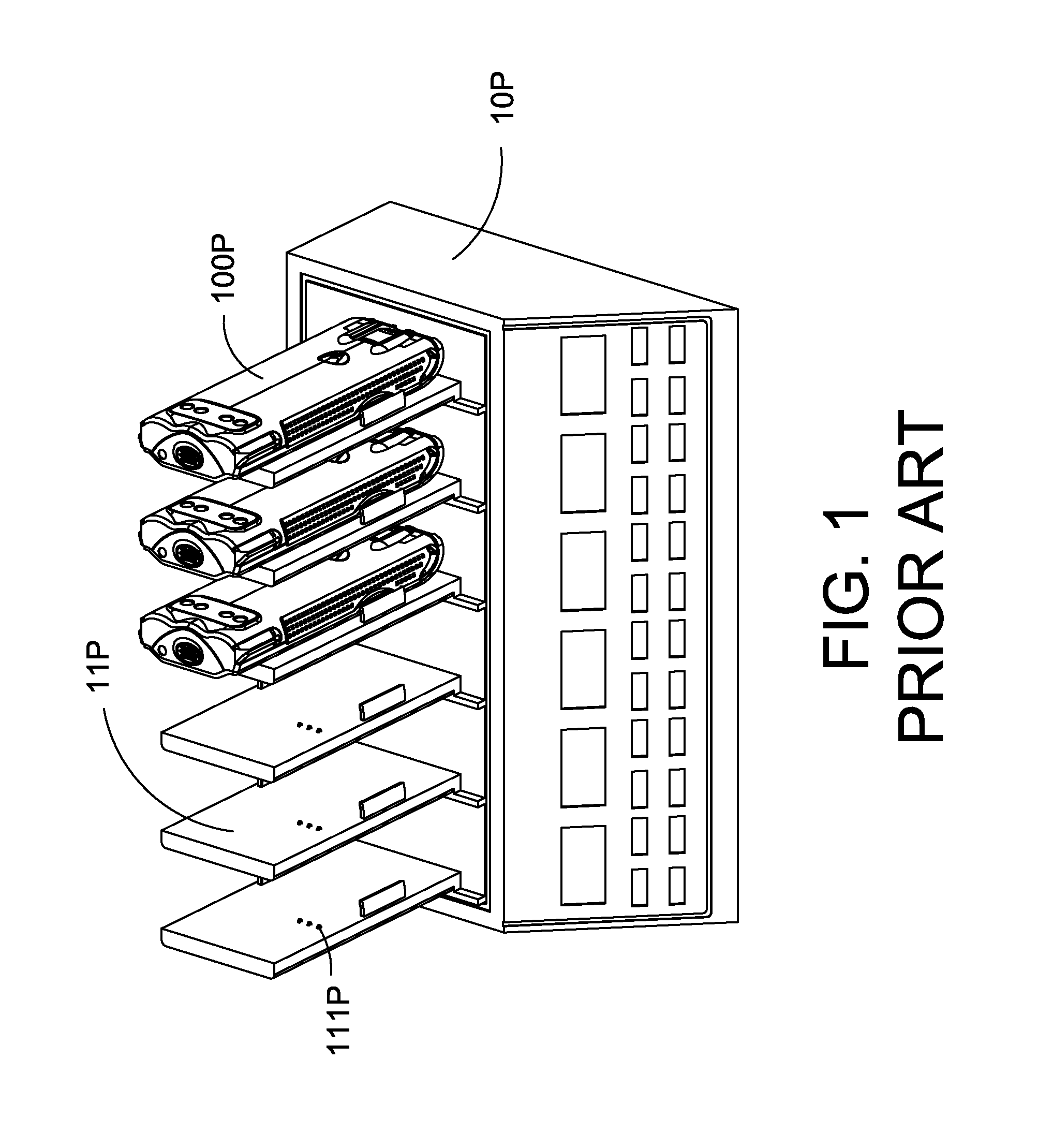
While discharging and testing of a rechargeable battery 100P may prolong the general life span of it, an analyzer is usually very expensive and is not suitable for widespread use.
However, conventional chargers do not perform discharging of the rechargeable batteries 100P and incapable of testing the condition of those batteries 100P.
When the rechargeable battery 100P is recharged in such a manner, the general life span of the rechargeable battery 100P is substantially limited.
Given the disadvantages of a conventional analyzer 10P (as described above), the user is thereby discouraged from buying and using the analyzer 10P.
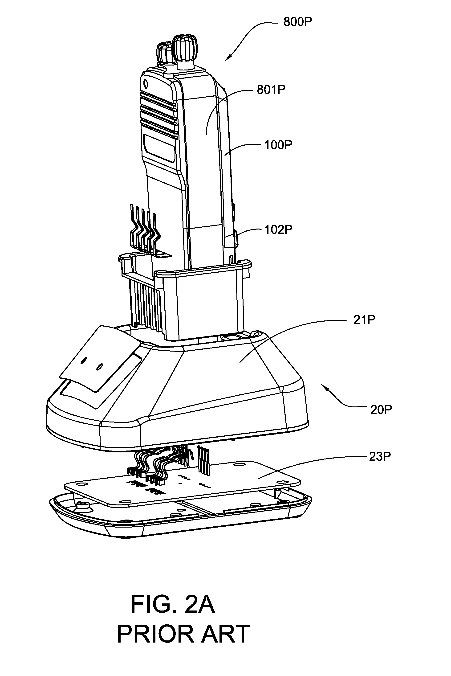
This procedure possesses a great deal of inconvenience for users using both the charger 20P and the analyzer 10P.

Method used


Image

  • Charger with Analyzer Arrangement
  • Charger with Analyzer Arrangement
  • Charger with Analyzer Arrangement

Examples


Embodiment Construction

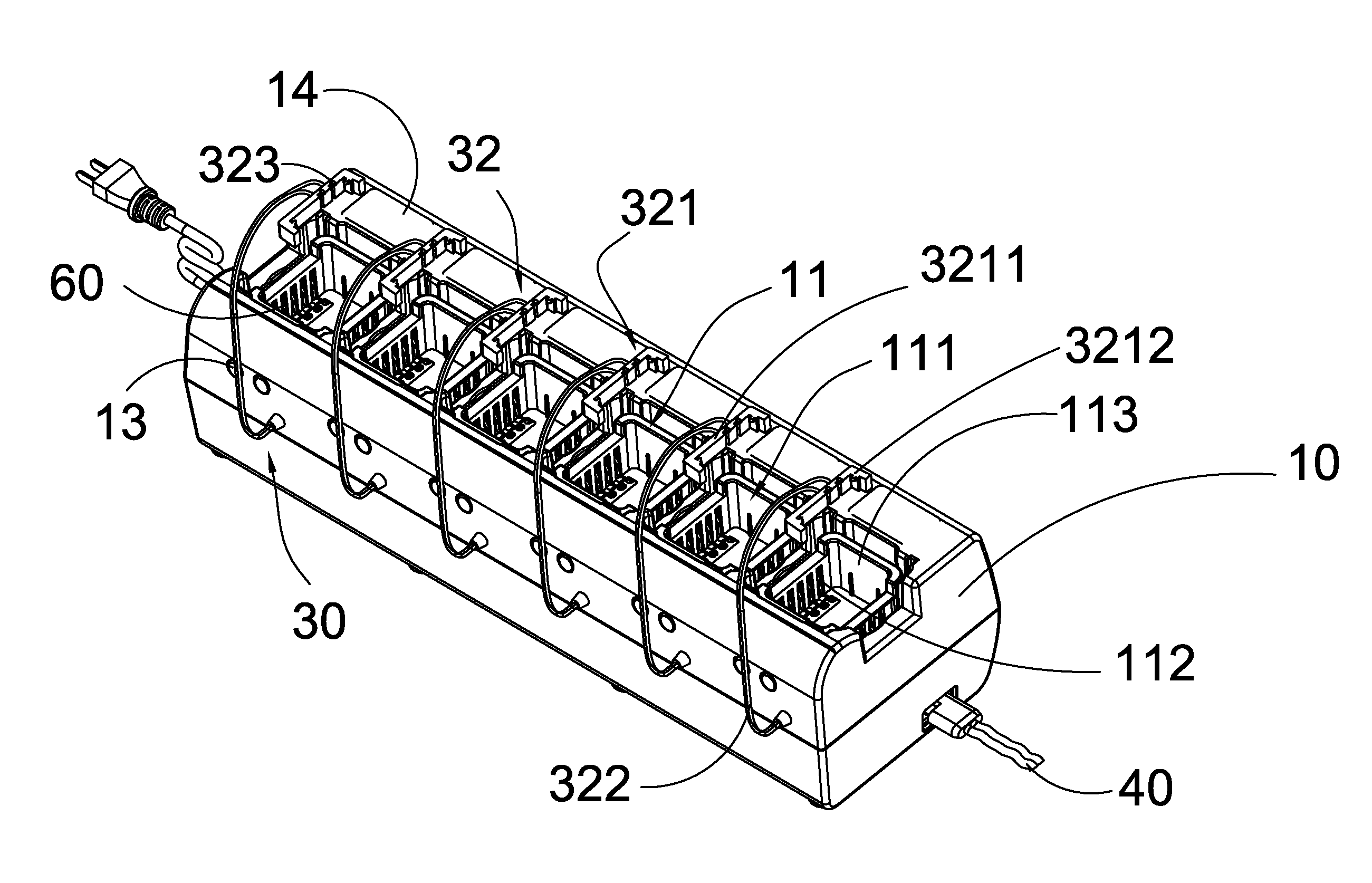
[0033]Referring to FIG. 3A, FIG. 3B, FIG. 4 to FIG. 10 of the drawings, a charger for charging at least one rechargeable battery 1 having a plurality of battery charging terminals 2 and battery discharging terminals 3 spacedly provided at predetermined positions on the rechargeable battery 1 is illustrated. The charger according to the preferred embodiment of the present invention comprises a charger base 10, a charging circuitry 20, and an analyzer arrangement 30. The rechargeable battery 1 is for an electrical appliance, preferably a radio communication device 70 which is capable of communicating with another radio communication device 70 through a predetermined radio frequency.

[0034]According to the preferred embodiment of the present invention, the charger is for use in conjunction with a rechargeable battery 1 where the battery charging terminals 2 and the battery discharging terminals 3 are spacedly provided at two different (and normally opposed) sides of the rechargeable bat...


PUM


Abstract

A charger includes a charger base, a charging circuitry, and an analyzer arrangement. The charger base includes at least one charging platform defining a receiving cavity. The analyzer arrangement includes an analyzing circuitry and an analyzer connector. The analyzer connector is provided on the charger base for electrically connecting the battery discharging terminals with the analyzing circuitry, wherein the charger is arranged to operate in at least one of a charger mode and an analyzer mode. In the charger mode, the rechargeable battery is arranged to insert in the receiving cavity in for charging the rechargeable by the charging circuitry. In the analyzer mode, the rechargeable battery is arranged to insert into the receiving cavity while the analyzer connector is extended from the charger base to electrically contact with the battery discharging terminals for allowing the rechargeable battery to be discharged and tested by the analyzing circuitry.

Description

BACKGROUND OF THE PRESENT INVENTION[0001]1. Field of Invention[0002]The present invention relates to a charger, and more particularly to a charger comprising an analyzer arrangement which allows the charger to operate between a charger mode and an analyzer mode.[0003]2. Description of Related Arts[0004]As shown in FIG. 1 of the drawings, a conventional analyzer, such as an analyzer for testing a rechargeable battery 100P of a radio communication device 800P (as shown in FIG. 2), mainly comprises an analyzer housing 10P having a plurality of battery platforms 11P indently formed thereon, an analyzing circuitry provided in the analyzer housing 10P. The analyzer housing 10P usually comprises a plurality of electrical terminals 111P provided on a corresponding position of each of the battery platforms 11P such that when the rechargeable battery 100P is inserted into one of the battery platforms 11P, discharging terminals of the rechargeable battery 100P is arranged to be aligned and in ...

Claims


Application Information

Patent Timeline
IPC IPC(8): H02J7/00
CPCH02J7/0047H02J7/0042H02J7/005
Inventor LAW, KING YIU
Owner DACA ELECTRONICS
Learn More