Vehicle mirror apparatus

a technology for mirrors and vehicles, applied in the direction of mirrors, instruments, mountings, etc., can solve the problem of less resistance of the vehicle mirror apparatus to the external environmen

Active Publication Date: 2011-08-11
KK TOKAI RIKA DENKI SEISAKUSHO
View PDF3 Cites 9 Cited by
  • Summary
  • Abstract
  • Description
  • Claims
  • Application Information

AI Technical Summary

Benefits of technology

[0027]Since the driving member is arranged on an inner circumferential side of a pivoting surface, the pivoting surface may be made larger so that pivot of the pivoting member may be stabilized.

Problems solved by technology

Thus, dust or the like from an external environment is likely to get in a sliding area between the sliding part and the receiving portion, making the vehicle mirror apparatus less resistant to the external environment.

Method used


Image

  • Vehicle mirror apparatus
  • Vehicle mirror apparatus
  • Vehicle mirror apparatus

Examples


Embodiment Construction

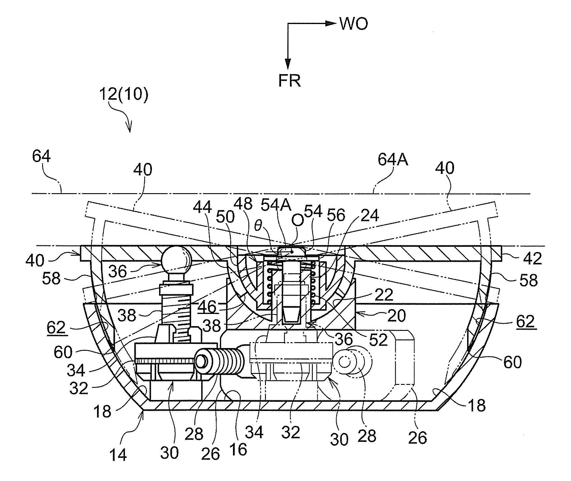
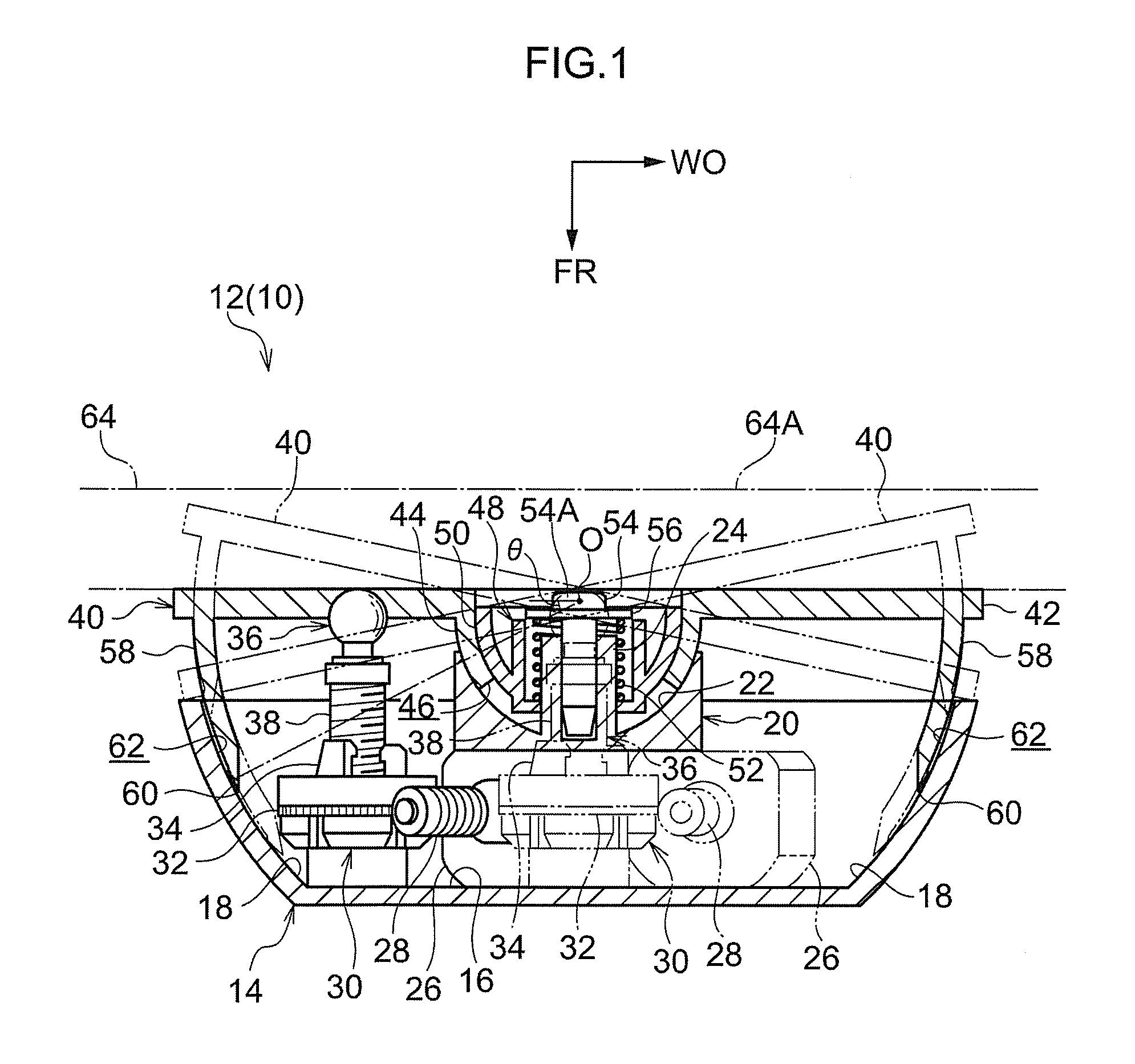
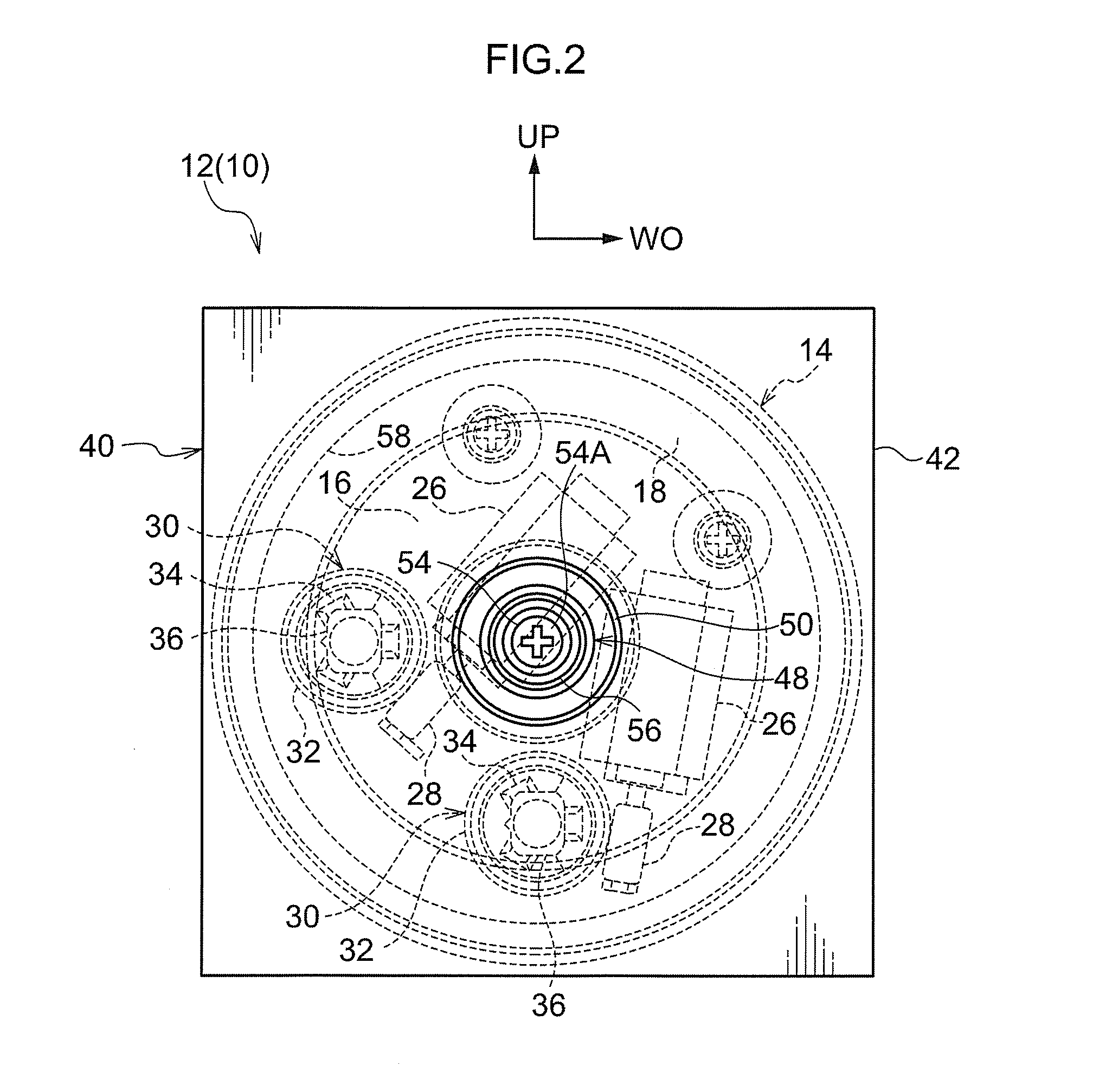
[0034]FIG. 1 shows main components of a vehicle door mirror apparatus 10 according to an exemplary embodiment of a vehicle mirror apparatus of the invention as a sectional view when viewed from below. FIG. 2 shows main components of the vehicle door mirror apparatus 10 as a front view when viewed from a rear position of the vehicle. FIG. 3 shows main components of the vehicle door mirror apparatus 10 as an exploded perspective view when viewed in a diagonal direction from lower side of the rear position of the vehicle. In the drawings, the front direction of the vehicle is indicated by an arrow FR, a width direction by an arrow WO, and the upward direction by an arrow UP.

[0035]The vehicle door mirror apparatus 10 is installed at a door of the vehicle and a mirror surface angle adjusting apparatus 12 is provided inside the vehicle door mirror apparatus 10.

[0036]As shown in FIGS. 1 to 3, the mirror surface angle adjusting apparatus 12 includes a case 14 in a substantially semispherica...


PUM


Abstract

A vehicle mirror apparatus comprising a mirror provided at a vehicle; a pivoting member holding the mirror; a sliding part provided at the pivoting member; a holding member pivotably holding the pivoting member, whereby an angle of a mirror surface of the mirror is adjusted; and a pivoting surface provided at the holding member. The sliding part is made slidable on the pivoting surface while a gap is provided between an edge of the holding member at a side of the pivoting member and the pivoting member in a pivoting radial direction of the pivoting member.

Description

CROSS-REFERENCE TO RELATED APPLICATION[0001]This application claims priority under 35 USC 119 from Japanese Patent Application, No. 2010-025593 filed Feb. 8, 2010, the disclosure of which is incorporated by reference herein.BACKGROUND OF THE INVENTION[0002]1. Technical Field[0003]The invention relates to a vehicle mirror apparatus in which a mirror surface angle is adjusted by pivot of a pivoting member by which the mirror is held.[0004]2. Related Art[0005]In a mirror surface angle adjusting apparatus described in WO 2006 / 040799, a mirror is mounted on a pivot plate and the pivot plate is held pivotably in a housing. The mirror surface angle of the mirror is adjusted by the pivot plate being driven and pivoted.[0006]Further, a sliding part is provided in the pivot plate and a receiving portion is formed in the housing so that the sliding part is slid on the receiving portion when the pivot plate is pivoted.[0007]In the mirror surface angle adjusting apparatus, the sliding part is cu...

Claims


Application Information

Patent Timeline
Patent Type & Authority Applications(United States)
IPC IPC(8): B60R1/02
CPCB60R1/072
Inventor KUDO, NOBUHIROSUMI, ISAO
Owner KK TOKAI RIKA DENKI SEISAKUSHO
Why Eureka
Try Eureka