
Floor cleaning apparatus

a technology for cleaning equipment and floors, applied in the direction of carpet cleaners, floor surfacing/polishing machines, cleaning machines, etc., can solve the problems of soiled mop and fluid in the bucket becoming contaminated by germs and/or bacteria, affecting the cleaning effect, etc., to achieve the effect of convenient use, increased maneuverability, and easy maneuverability

Inactive Publication Date: 2014-11-18
KARCHER NORTH AMERICA INC
View PDF414 Cites 22 Cited by
  • Summary
  • Abstract
  • Description
  • Claims
  • Application Information

AI Technical Summary

Benefits of technology

The present invention is a floor treatment apparatus that is easy to move around. It includes a chassis with an enclosure that holds the device's internal components and a platform for the operator. The apparatus can be equipped with a steering device for better maneuverability, a self-propelled wheel, or wheels that can rotate 360 degrees. The apparatus is also cost-effective to manufacture. These features make the floor treatment process more efficient and effective, and also safer and comfortable for the operator.

Problems solved by technology

Maintaining the cleanliness of these surfaces, especially in high volume areas in commercial, industrial, institutional and public buildings is an ongoing and time consuming process.
The prior devices address many issues that arise with cleaning such floored surfaces.
However, soon the mop and fluid in the bucket becomes soiled or otherwise contaminated by germs and / or bacteria.
From that point on, each time the worker plunges the mop into the bucket and rings the mop, both the mop and cleaning fluid become more dirty / contaminated.
While such equipment is maneuverable and is an improvement over the earlier mop and bucket technology, the system is still labor intensive and slow.
However, the distance between the scrub deck and squeegee is relatively great.
Also, walk behinds typically have relatively wide squeegees.
These characteristics limit such machine's maneuverability and limit the doorways they can easily pass through.
The problem with these side squeegees is they do not perform well for long and leave a film of water in turns because the vacuumized squeegee does not follow the true path of the scrub deck, only the path of the side squeegees (which leave the film of water).
Finally, side squeegee are typically heavy rubber blades and have significant down pressure applied to them to direct the water this makes them expensive and causes significant “drag” which increases the work for the propel unit and limits battery run time.
While more maneuverable than larger walk behind floor treatment machines, the small machines rarely clean as well as the larger machines.
Further, known cleaning machines do not provide adequate onboard storage for cleaning supplies, tools, etc.
Likewise, prior art machines rarely provide a flexible approach to adding storage facilities for trash and the like when the need for such arises.
These large ride-on machines are not particularly well-suited for cleaning smaller, more confined floor surfaces, which are often found in hallways, small rooms, or even large rooms which have many obstacles.
However, smaller devices are usually pushed or pulled by an operator.
Hence, the major drawback of these devices is they often rely on operator strength to maneuver the device.
After a long shift of walking behind a treatment device, the operator is bound to become fatigued, wherein his or her attention will deviate from the task at hand, possibly resulting in uneven treatment to the floored area.
Thus, a subsequent crew may have to return and retouch certain areas not accurately treated during the first operation.
Human errors related to the time a surface is exposed to a brush, may occur when the operator lingers over a single area for extended period of time.
This situation is never good for a floor surface.
The devices in the art are also difficult to maneuver and often are not adapted to operate around tight corners, wherein pre or post cleaning operations must be performed, thus increasing the time and expense of the entire task.
Prior art machines are constructed so the internal volume is minimized, providing a compact machine, but leaving virtually no easy access to internal componentry.
Removal of the external componentry and the housing segments technology is time consuming, costly, and increases the chance that the machine will be damaged or a component of the machine will be lost.

Method used


Image

  • Floor cleaning apparatus
  • Floor cleaning apparatus
  • Floor cleaning apparatus

Examples


Embodiment Construction

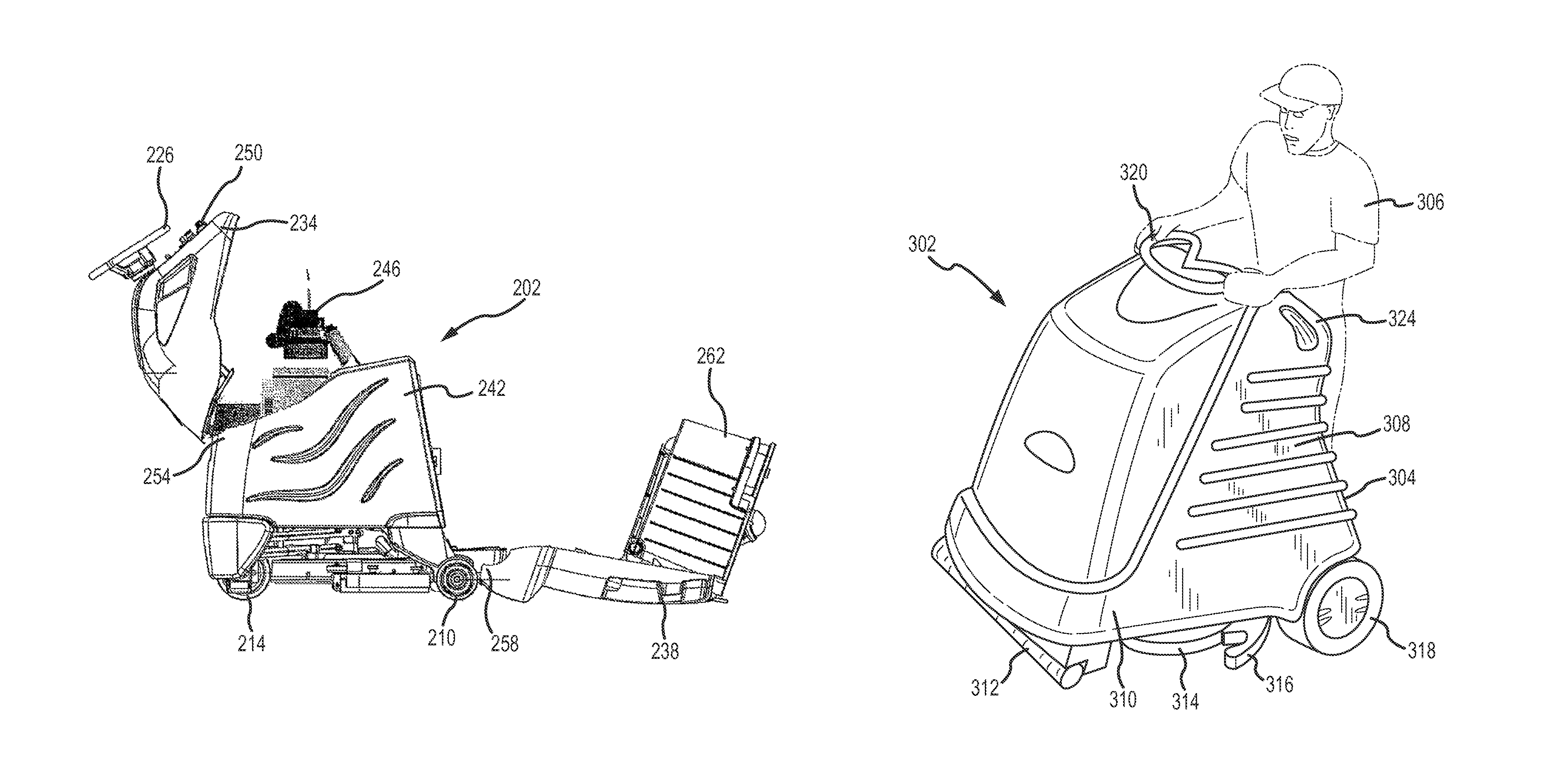
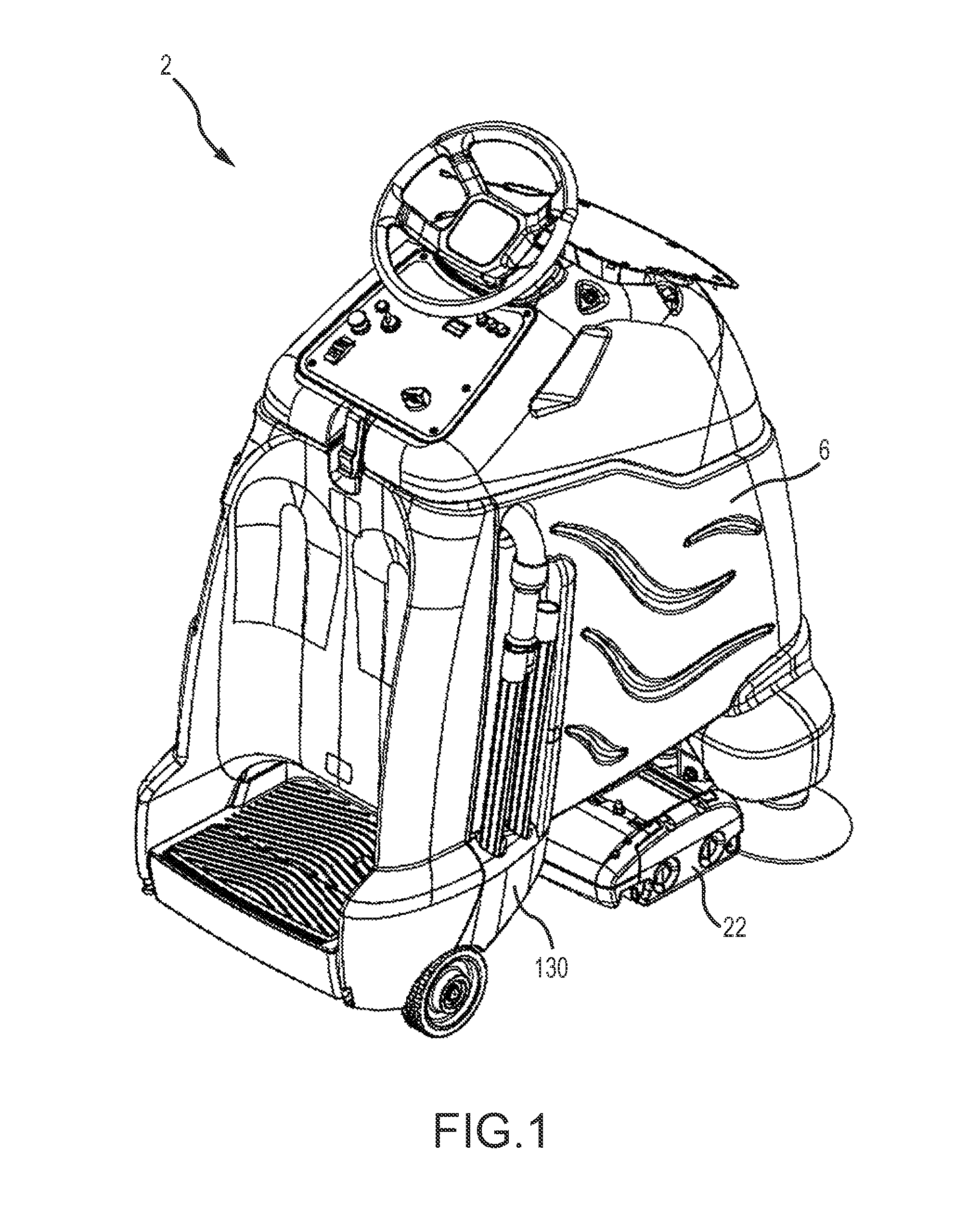
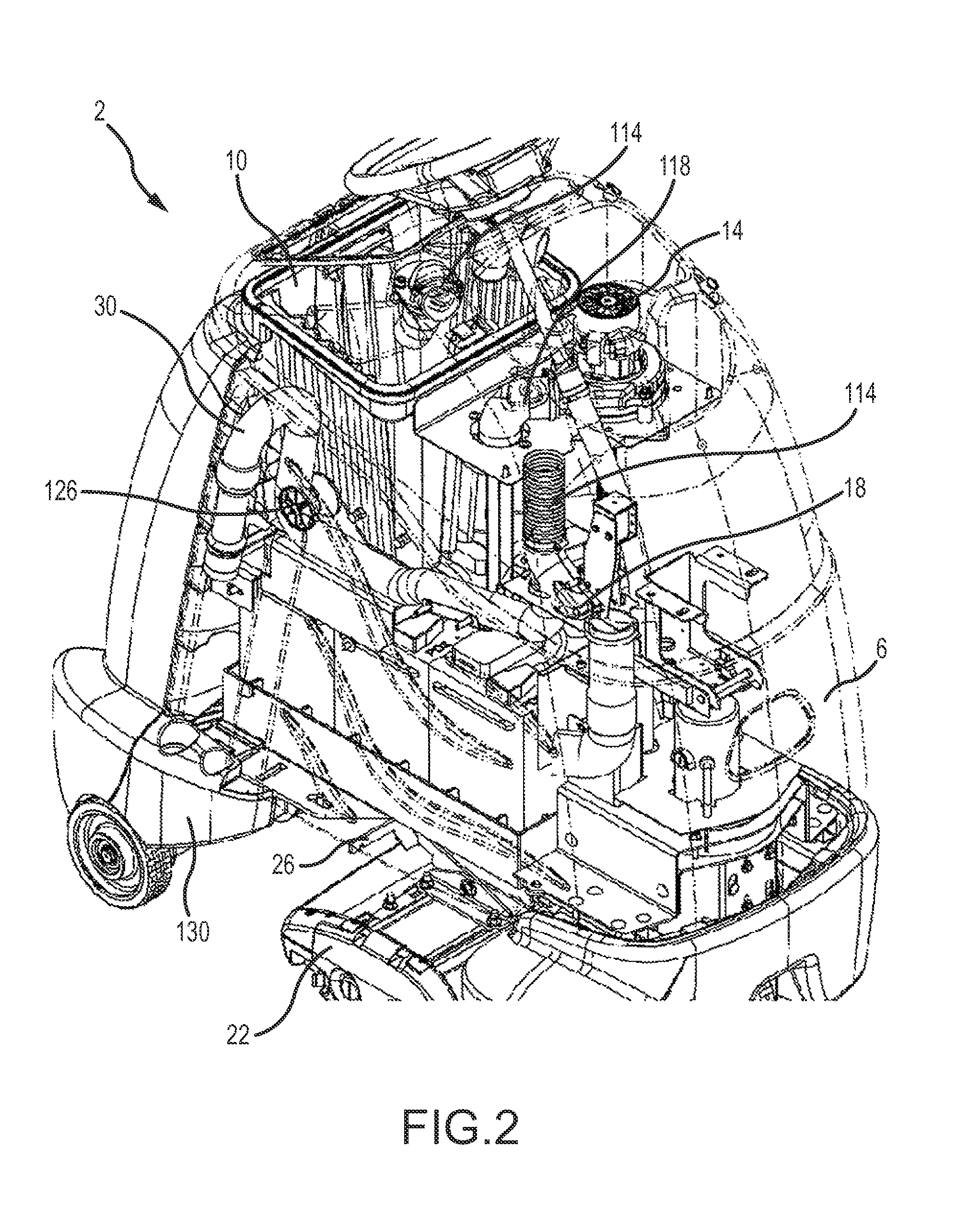
[0106]FIGS. 1-3 show a floor treatment apparatus 2 (“apparatus”) of one embodiment of the present invention that employs a housing 6 that covers a vacuum bag 10, a vacuum motor 14, a valve 18, and other components generally found in floor treatment apparatus. The apparatus 2 employs a cleaning assembly 22 attached to the housing 6 via a spring to an armature 26, which will be further described below. In operation, dirt, debris, and residue are agitated by the cleaning assembly 22 and suctioned into the vacuum bag 10. In a second mode of operation, a hand-held accessory hose 30 is used to suction debris in hard-to-reach places. The debris suctioned through the accessory hose 30 is also directed to the vacuum bag 10 by the vacuum motor 14.

[0107]Referring now to FIGS. 4-7, the cleaning assembly 22 employed by some embodiments of the present invention is shown that includes a front brush 34 and a rear brush 38. The front brush 34 and rear brush 38 may comprise a single, cylindrical brus...


PUM


Abstract

A floor treatment apparatus is provided that includes a chassis that supports at least one cleaning element. The chassis is supported by a plurality of wheels, one which is steerable via a steering wheel interconnected to a housing also associated with the chassis. The chassis provided includes a plurality of movable housing members, one of which is associated with the steering wheel. To access the internal components of the floor treatment apparatus, the front housing is rotated or moved away from the other housings wherein the steering wheel does not require disconnection to allow this movement.

Description

[0001]This application is related to U.S. Pat. No. 5,555,596, entitled “Floor cleaning apparatus”; U.S. Pat. No. 5,485,653, entitled “Floor cleaning apparatus”; U.S. Pat. No. 5,628,086, entitled “Floor cleaning apparatus with Squeegee Mounting System”; and U.S. Pat. No. 5,608,947, entitled “Floor cleaning apparatus with Pre-Filter”; the entire disclosures of which are incorporated by reference herein.[0002]This application is a continuation of U.S. patent application Ser. No. 12 / 912,554, filed Oct. 26, 2010, now abandoned, which is a continuation-in-part of U.S. patent application Ser. No. 11 / 868,353, filed Oct. 5, 2007, now U.S. Pat. No. 8,245,345, which is a continuation of U.S. patent application Ser. No. 11 / 059,663, filed Feb. 15, 2005, now U.S. Pat. No. 7,533,435, which is a continuation-in-part of abandoned U.S. patent application Ser. No. 10 / 737,027, filed Dec. 15, 2003, now abandoned, which is a continuation-in-part of abandoned U.S. patent application Ser. No. 10 / 438,485, f...

Claims


Application Information

Patent Timeline
Patent Type & Authority Patents(United States)
IPC IPC(8): A47L11/16A47L11/40A47L11/03A47L11/24
CPCA47L11/4044A47L11/4041A47L11/4066A47L11/24A47L11/4027
Inventor PEDLAR, ROGERPEARSON, DANIELSHARK, ERIC L.VENARD, DANIEL C.DOLL, BRIAN J.SIMMONS, RUSTYGREEN, NEVINTRAN, LOI X.GORSKY, ROBERT S.TUCKER, STEVEN W.LEIFHEIT, TODD
Owner KARCHER NORTH AMERICA INC
Learn More