Motion simulator

a simulator and motion technology, applied in simulators, amusements, instruments, etc., can solve the problems of high load applied to the motor, difficult to quickly and accurately control yaw, excessive weight of the apparatus, etc., to achieve easy installation and movement, more realistic virtual environments, and simple configuration

Active Publication Date: 2015-06-11
MOTION DEVICE
View PDF5 Cites 21 Cited by
  • Summary
  • Abstract
  • Description
  • Claims
  • Application Information

AI Technical Summary

Benefits of technology

[0022]According to the present invention, since a motion simulator is provided with a rotating plate on which a plurality of casters and a motor are mounted and a fixing plate supporting the rotating plate to enable the rotating plate to be rotated and having a driven part fixedly mounted thereon and meshed with a shaft of the motor, it becomes easy to install and move the motion simulator.
[0023]In addition, the motion simulator of the present invention stably realizes various simulations of the motion with a simple configuration to enable a user to experience more realistic virtual environments.
[0024]Also, a chain is connected to a first sprocket coupled to the shaft of the motor mounted on one side of the rotating plate and a plurality of second sprockets fixed to an upper surface of the fixing plate to allow yaw to be performed through an operation of the motor so that a load applied to the motor can be reduced and yaw can be quickly and accurately realized.

Problems solved by technology

Therefore, there is a drawback in that, since an inertial force is increased when the base plate 2 is rotated, if a rotational direction of the base plate 2 is reversed, a high load is applied to the motor 81 and it is difficult to quickly and accurately control yaw.
In addition, the conventional motion simulator has problems in that, since the lower supporting structure is composed of the pedestal 1 and the base plate 2, the apparatus has an excessive weight, and since the pedestal 1 is configured to be placed on a floor of an installation site, it is not easy to move the motion simulator.

Method used


Image

  • Motion simulator
  • Motion simulator
  • Motion simulator

Examples


Embodiment Construction

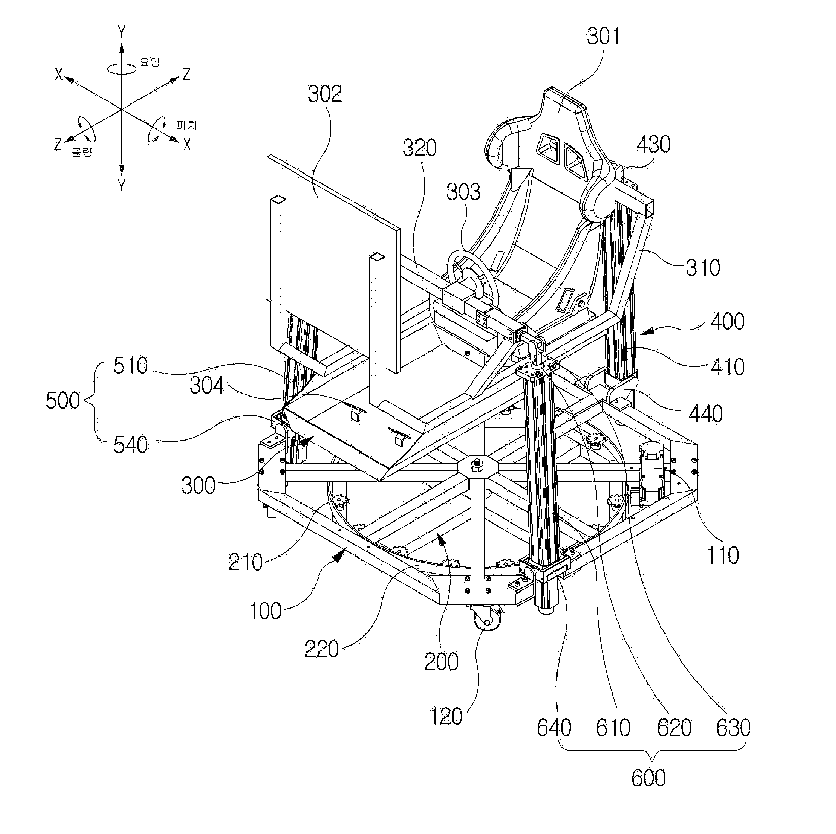
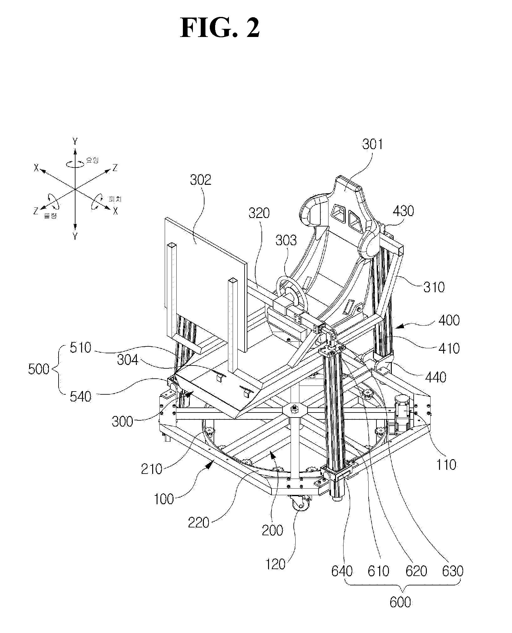
[0041]Exemplary embodiments of the present invention will be described in detail below with reference to the accompanying drawings. While the present invention is shown and described in connection with exemplary embodiments thereof, it will be apparent to those skilled in the art that various modifications can be made without departing from the spirit and scope of the invention. In description of the movement directions, as shown in FIG. 2, roll is described as rotational movement with a forward / rearward direction (Z axis) as a rotational center, pitch is described as rotational movement with a right / left direction (X axis) as a rotational center and yaw is described as rotational movement with an upward / downward direction (Y axis) as a rotational center.

[0042]Referring to FIG. 2 to FIG. 5, a motion simulator according to the present invention includes a rotating plate 100 on which a motor 110 is mounted through one side thereof and on which a plurality of casters 120 are mounted th...


PUM


Abstract

An object of the present invention is to provide a motion simulator which, despite having a simple structure, can realize various types of simulation motion and is easily installed and moved. The motion simulator of the present invention includes a rotating plate on which a motor is mounted through one side thereof and on which a plurality of casters are mounted through a lower surface thereof, the caster being configured such that, when the motion simulator is used, rotation of the caster is inhibited to allow the wheel to roll in the rotational direction of the rotating plate, and when the motion simulator is moved, the caster can be unlocked to enable the caster to rotate and the motion simulator to be freely pushed and moved; a fixing plate supporting a lower portion of the rotating plate to enable the rotating plate to be rotated and having a driven part fixedly mounted thereon and meshed with a shaft of the motor; an operating frame disposed at and spaced apart from an upper portion of the rotating plate; and a plurality of link units coupled between the rotating plate and the operating frame to support and vertically move the operating frame.

Description

CROSS-REFERENCE TO RELATED APPLICATIONS[0001]This application is a continuation of International Application No. PCT / KR2013 / 003088 filed on Apr. 12, 2013 which claims priority to Korean Application No. 10-2012-0094228 filed on Aug. 28, 2012, which applications are incorporated herein by reference.TECHNICAL FIELD[0002]The present invention relates to a motion simulator, and more particularly, to a motion simulator which, despite having a simple structure, can stably perform various types of simulation motion and is easily installed and moved.BACKGROUND ART[0003]In general, a motion simulator is a device for reproducing a dynamic change in response to a virtual environment controlled by a computer to enable a user to feel motion in virtual reality as if it were real motion. Such motion simulators can realize a flight simulation or a driving simulation and have recently been widely used as simulators for games or simulators for theaters that enable people to feel three-dimensional moti...

Claims


Application Information

Patent Timeline
Patent Type & Authority Applications(United States)
IPC IPC(8): A63G31/16
CPCA63G31/16G09B9/02G09B9/00
Inventor LEE, JONG CHANKANG, YU SINCHUN, SANG GON
Owner MOTION DEVICE
Why Eureka
Try Eureka