Protection Circuit for Protecting an Intermediate Circuit of a Solar Inverter Against Overvoltages

a technology of solar inverters and protection circuits, which is applied in emergency protection arrangements for limiting excess voltage/current, power conversion systems, electrical equipment, etc., can solve the problems of inverters and in particular their overvoltage-sensitive semiconductor switches being destroyed within a very short time, and the applied array voltage is no longer regulated, so as to achieve the effect of simple circuit design of electronic voltage limiters

Inactive Publication Date: 2011-08-11
SIEMENS AG
View PDF5 Cites 25 Cited by
  • Summary
  • Abstract
  • Description
  • Claims
  • Application Information

AI Technical Summary

Benefits of technology

[0021]In accordance with a preferred embodiment, the comparator comprises a chopper for regulated clocked control of the electronic switching element. The particular advantage is that only a comparatively small power loss occurs in the switching element, while by far the greatest majority of the electrical power is dropped in the input element for voltage limiting. The latter is preferably a resistor, for example a power resistor. The electronic switching element is normally a transistor.
[0022]Furthermore, the chopper may have a pulse width modulator for regulated clocked control of the electronic switching element at a constant switching frequency. The circuitry design of the electronic voltage limiter is therefore particularly simple.

Problems solved by technology

However, if a fault occurs in the inverter and this now blocks the control pulses for controlling the semiconductor switches in the inverter power section, then the applied array voltage is no longer regulated.
However, if the array voltage rises during this time to unacceptably high voltage values beyond the voltage limit value, then the inverter and in particular its overvoltage-sensitive semiconductor switch will be destroyed within a very short time.

Method used


Image

  • Protection Circuit for Protecting an Intermediate Circuit of a Solar Inverter Against Overvoltages
  • Protection Circuit for Protecting an Intermediate Circuit of a Solar Inverter Against Overvoltages
  • Protection Circuit for Protecting an Intermediate Circuit of a Solar Inverter Against Overvoltages

Examples


Embodiment Construction

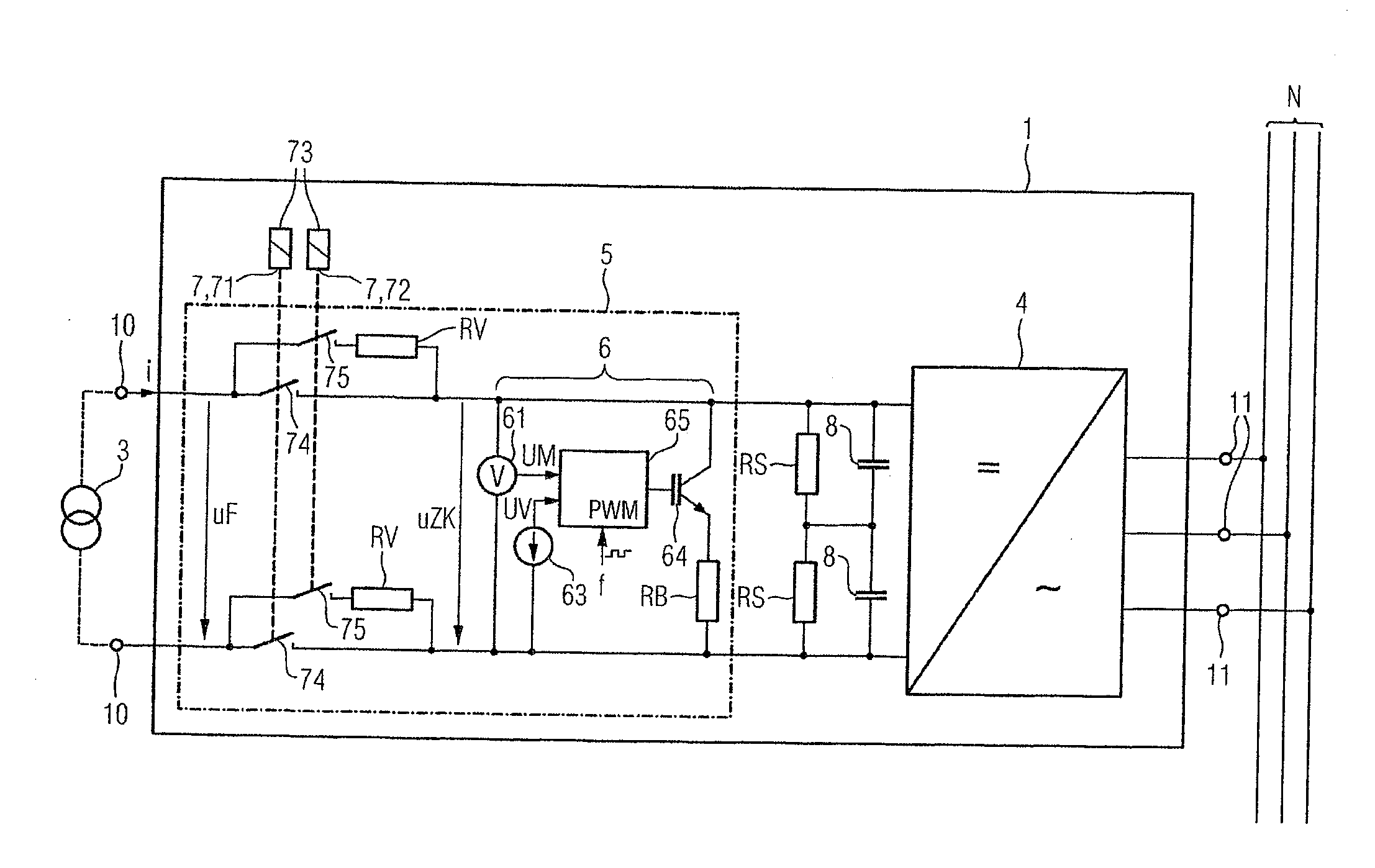
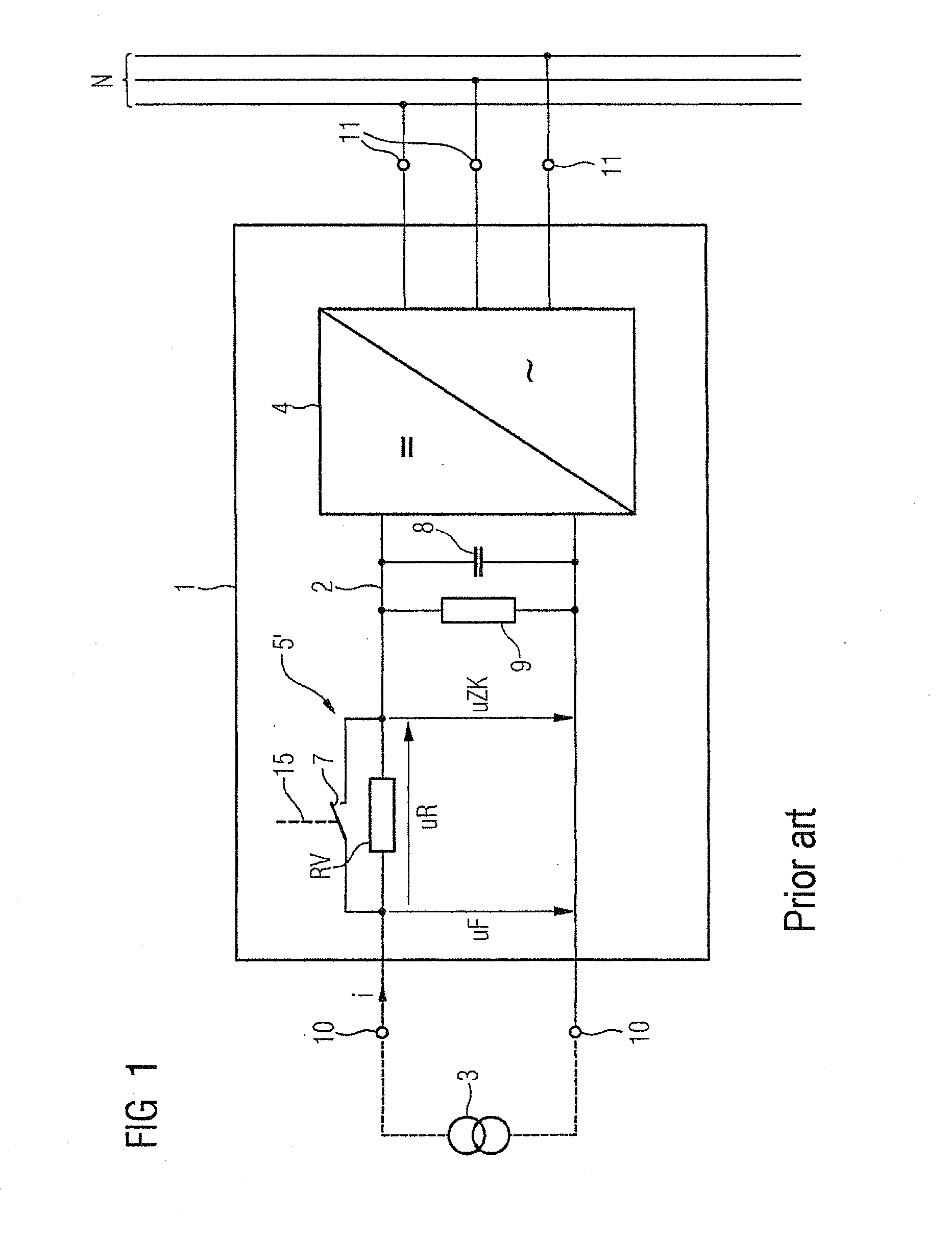
[0032]By way of example, FIG. 1 shows an inverter 1 having an input-side protection circuit 5′ in accordance with the prior art for protection of the intermediate circuit 2 of the inverter 1 against overvoltages. In the example shown in FIG. 1, the reference symbol 1 denotes an inverter which is known per se. On the input side the inverter 1 has a voltage intermediate circuit 2, consisting of an intermediate-circuit capacitor 8 and an intermediate-circuit resistor RS as connected in parallel. By way of example, the resistor may be a discrete component. The intermediate-circuit resistor RS may also be a discharge resistor for direct-contact protection. Furthermore, the intermediate circuit 2 is intended for connection to a regenerative DC voltage source 3, such as to a solar array.

[0033]A power section 4 for feeding an electrical power supply system N is connected downstream of the output side of the intermediate circuit 2. The power section 4 converts an applied intermediate-circuit...


PUM


Abstract

An input-side protective circuit for protecting an intermediate circuit of an inverter against overvoltages, wherein the input-side protective circuit includes an upstream element for limiting the voltage of the intermediate circuit connected upstream of the intermediate circuit and which is bridgeable by a mechanical switching device that is controllable such that it opens in a feed-in operation of the inverter when an intermediate circuit voltage is greater than a specified voltage limit. The protective circuit also includes an electronic voltage limiter connected downstream of the upstream element and connected in parallel to the intermediate circuit.

Description

CROSS-REFERENCE TO RELATED APPLICATIONS[0001]This is a U.S. national stage of International Application No. PCT / EP2009 / 061614, filed on 8 Sep. 2009. This patent application claims the priority of German patent application DE 10 2008 050 543.9 filed 6 Oct. 2008, the content of which application is incorporated herein by reference.BACKGROUND OF THE INVENTION[0002]1. Field of the Invention[0003]The invention relates to an input-side protection circuit for protecting an intermediate circuit of an inverter against overvoltages, with the protection circuit having an input element, which is connected upstream of the intermediate circuit and is bridgeable by a controllable mechanical switching device, for voltage limiting in the intermediate circuit, and with the mechanical switching device being controllable such that it opens in a feed mode for the inverter when an intermediate-circuit voltage is greater than a predetermined voltage limit value.[0004]The invention furthermore relates to a...

Claims


Application Information

Patent Timeline
Patent Type & Authority Applications(United States)
IPC IPC(8): H02H9/04
CPCH02M1/32H02H7/1222
Inventor SCHAUB, UWESCHMITT, WOLFGANGWEIDAUER, JENS
Owner SIEMENS AG
Why Eureka
Try Eureka