Polar modulation transmission apparatus and wireless communication apparatus

a transmission apparatus and wireless communication technology, applied in the direction of modulation, simultaneous amplitude and angle modulation, amplifier combinations, etc., can solve the problems of increasing the power loss of the whole apparatus, not giving sufficient consideration to the power loss at dc/dc, etc., to reduce the power loss at the amplitude signal amplifying section, reduce the power loss, and reduce the power loss. effect of battery supply line power loss

Inactive Publication Date: 2008-11-25
PANASONIC CORP
View PDF7 Cites 20 Cited by
  • Summary
  • Abstract
  • Description
  • Claims
  • Application Information

AI Technical Summary

Benefits of technology

[0016]It is therefore an object of the present invention to provide polar modulation transmission apparatus capable of suppressing power loss of a battery supply line to a high-frequency power amplifier regardless of whether transmission power is high or low and to provide wireless communication apparatus of low power loss. The present invention achieves the aforementioned object by providing polar modulation transmission apparatus with: a high frequency power amplifying section capable of subjecting a phase modulated high frequency signal to power amplification according to a voltage applied to a battery terminal of the high frequency power amplifying section; an amplitude signal amplifying section, amplifying and applying to the battery terminal of the high frequency power amplifying section an amplitude modulation signal according to a voltage value applied from a battery to a battery terminal of the amplitude signal amplifying section; a battery voltage conversion section converting and applying to the battery terminal of the amplitude signal amplifying section a battery voltage from the battery in such a manner that power loss at the amplitude signal amplifying section becomes small; and an operation control section causing the battery voltage conversion section to operate so as to apply the battery voltage converted by the battery voltage conversion section to the battery terminal of the amplitude signal amplifying section or halt operation of the battery voltage conversion section so as to apply the battery voltage from the battery directly, based on a transmission power value.

Problems solved by technology

However, the configuration of the related art shown in FIG. 1 does not give sufficient consideration to power loss at DC / DC converter 16.
Providing of the DC / DC converter 16 therefore conversely increases power loss of the whole of the apparatus.

Method used


Image

  • Polar modulation transmission apparatus and wireless communication apparatus
  • Polar modulation transmission apparatus and wireless communication apparatus
  • Polar modulation transmission apparatus and wireless communication apparatus

Examples


first embodiment

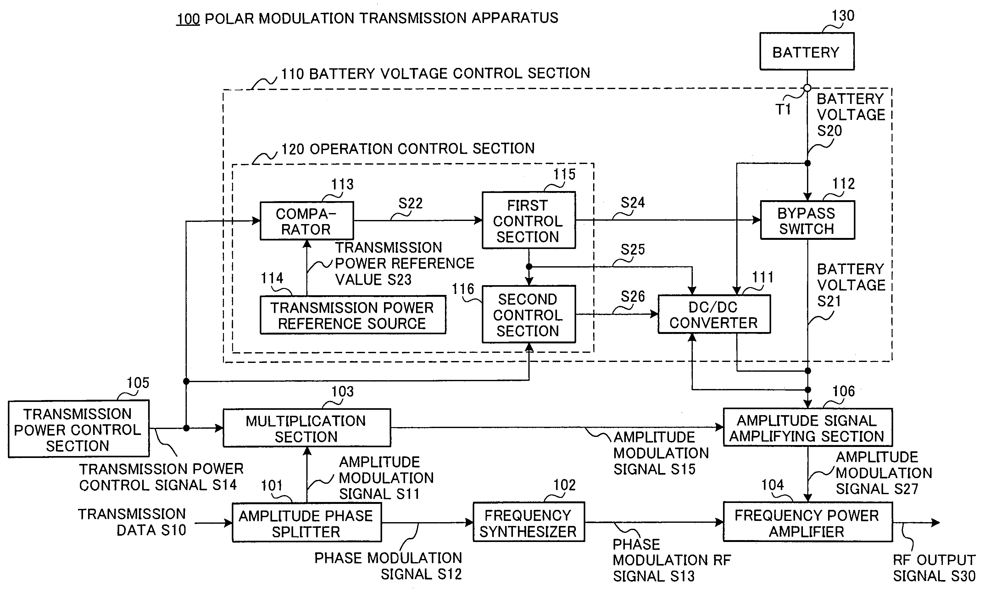
[0028]FIG. 3 shows a configuration for polar modulation transmission apparatus of this embodiment. Polar modulation transmission apparatus 100 is used, for example, in mobile terminals of mobile communication systems, or in base station apparatus carrying out wireless communication with mobile terminal apparatus.

[0029]Polar modulation transmission apparatus 100 inputs transmission data S10 to amplitude phase splitter 101. Amplitude phase splitter 101 forms amplitude modulation signal S11 (for example, √(I2+Q2)) and phase modulation signal S12 expressing transmission data S10 in polar coordinates, and sends amplitude modulation signal S11 to multiplication section 103 and phase modulation signal S12 to frequency synthesizer 102. Frequency synthesizer 102 forms phase modulation RF signal S13 by modulating a carrier wave using phase modulation signal S12, and transmits this to a signal input terminal of frequency power amplifier 104.

[0030]In addition to amplitude modulation signal S1, ...

second embodiment

[0050]A configuration for a polar modulation transmission apparatus of this embodiment is shown in FIG. 5, with portions corresponding to FIG. 3 being given the same numerals. Polar modulation transmission apparatus 200 is such that the configuration of operation control section 210 of battery voltage control section 201 is different compared to polar modulation transmission apparatus 100 of FIG. 3.

[0051]Operation control section 210 has a monitoring section 202 monitoring battery voltage S20 of battery 130. Monitoring section 202 is inputted with battery voltage S20 of battery 130 and battery voltage reference value S200 from battery voltage reference source 203.

[0052]When battery voltage S20 becomes larger than battery voltage reference value S200, monitoring section 202 sends detection signal S201 indicating this to first control section 115. When detection signal S201 indicating that battery voltage S20 has become larger than battery voltage reference value S200 is inputted, fir...

third embodiment

[0059]A configuration for a polar modulation transmission apparatus of this embodiment is shown in FIG. 7, with portions corresponding to FIG. 3 being given the same numerals. Polar modulation transmission apparatus 300 is such that the configuration of operation control section 310 of battery voltage control section 301 is different compared to polar modulation transmission apparatus 100 of FIG. 3.

[0060]Operation control section 310 has a battery voltage table 302 that second control section 116 refers to while controlling the battery voltage conversion operation of DC / DC converter 111.

[0061]As shown in FIG. 8A, battery voltage table 302 associates designated transmission power values (corresponding to transmission power control signal S14) and battery voltage setting values. Battery voltage table 302 sends battery voltage setting value S301 corresponding to the inputted transmission power control signal S14 to second control section 116. Battery voltage setting values stored in ba...


PUM


Abstract

Polar modulation transmission apparatus capable of suppressing power loss of a battery supply line to a high-frequency power amplifier regardless of whether transmission power is high or low is provided. Operation control section (120) performing control in such a manner that a battery voltage (S21) converted as a result of operation of a DC / DC converter (111) is applied to amplitude signal amplifying section (106) or halting operation of the DC / DC converter (111) in such a manner that battery voltage (S20) is applied directly from the battery (130) based on a transmission power control signal (S14). As a result, when transmission power is low, power loss at the amplitude signal amplifying section (106) is suppressed by DC / DC converter (111), unnecessary operation of DC / DC converter (111) is halted when transmission power is high, and power loss can be suppressed regardless of whether transmission power is high or low.

Description

BACKGROUND OF THE INVENTION[0001]1. Field of the Invention[0002]The present invention relates to polar modulation transmission apparatus, and particularly relates to polar modulation transmission apparatus and wireless communication apparatus employing this apparatus, provided with an amplitude modulation amplifying section amplifying an amplitude modulation signal according to a battery voltage, and applied with an amplitude modulation signal amplified by the amplitude modulation amplifying section as a battery voltage for a high-frequency power amplifier amplifying power of a phase-modulated high-frequency signal, that may be widely applied, for example, to wireless equipment carrying out wireless communication of a polar modulation scheme such as, for example, communication terminals such as mobile telephones, or base stations, etc.[0003]2. Description of the Related Art[0004]In the related art, a polar modulation method is proposed as technology capable of providing both high po...

Claims


Application Information

Patent Timeline
Patent Type & Authority Patents(United States)
IPC IPC(8): H04B1/02
CPCH03C5/00H04B1/0475
Inventor ARAYASHIKI, MAMORU
Owner PANASONIC CORP
Why Eureka
Try Eureka