Fluid heater

Inactive Publication Date: 2011-08-11
TSINGHUA UNIV +1
View PDF15 Cites 18 Cited by
  • Summary
  • Abstract
  • Description
  • Claims
  • Application Information

AI Technical Summary

Problems solved by technology

However, because the fluid flows in the cavity, the heat of the fluid will be conducted from the outer pipe to outside, and the heating efficiency of the fluid heater will be adversely affected.
As such, the fluid heater h

Method used


Image

  • Fluid heater
  • Fluid heater
  • Fluid heater

Examples


Embodiment Construction

[0017]The disclosure is illustrated by way of example and not by way of limitation in the figures of the accompanying drawings in which like references indicate similar elements. It should be noted that references to “an” or “one” embodiment in this disclosure are not necessarily to the same embodiment, and such references mean at least one.

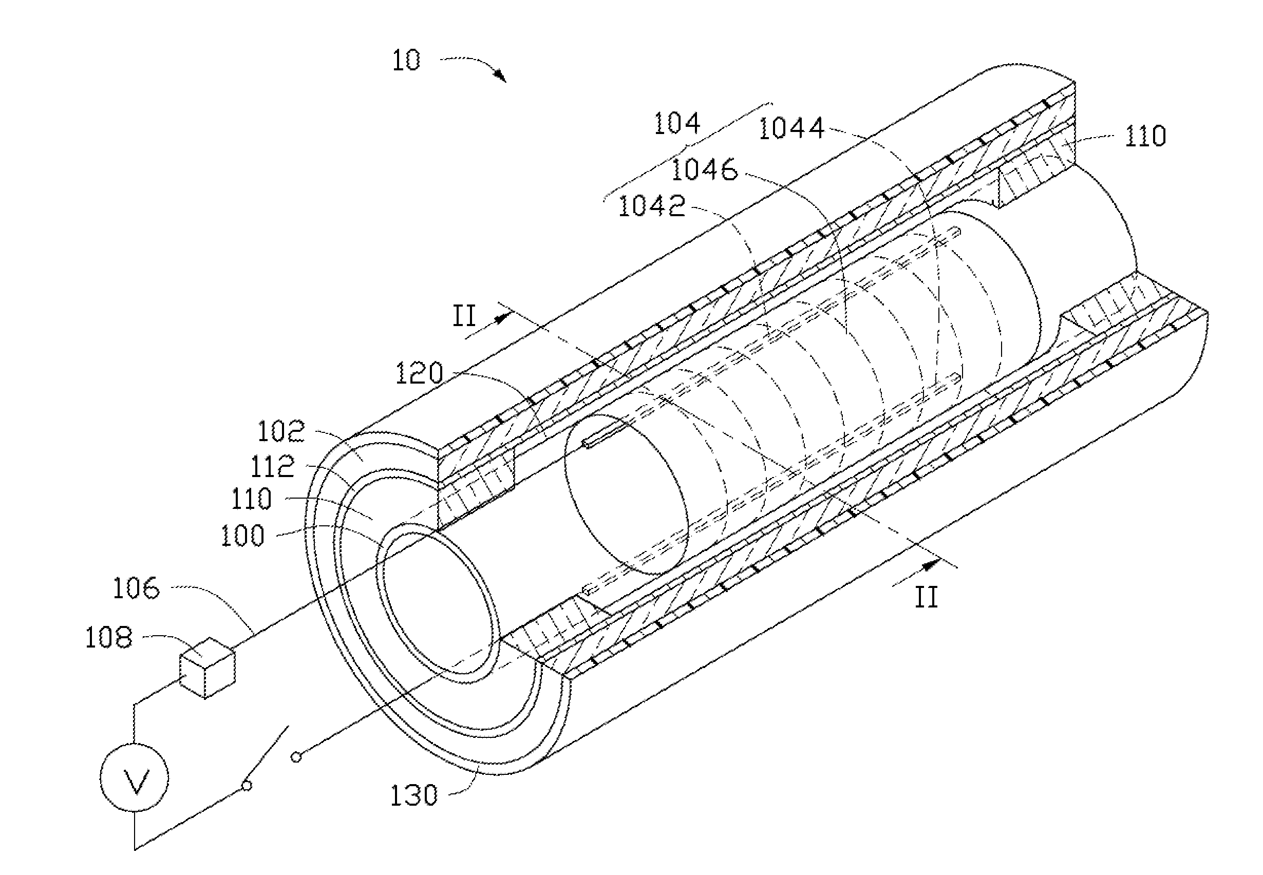
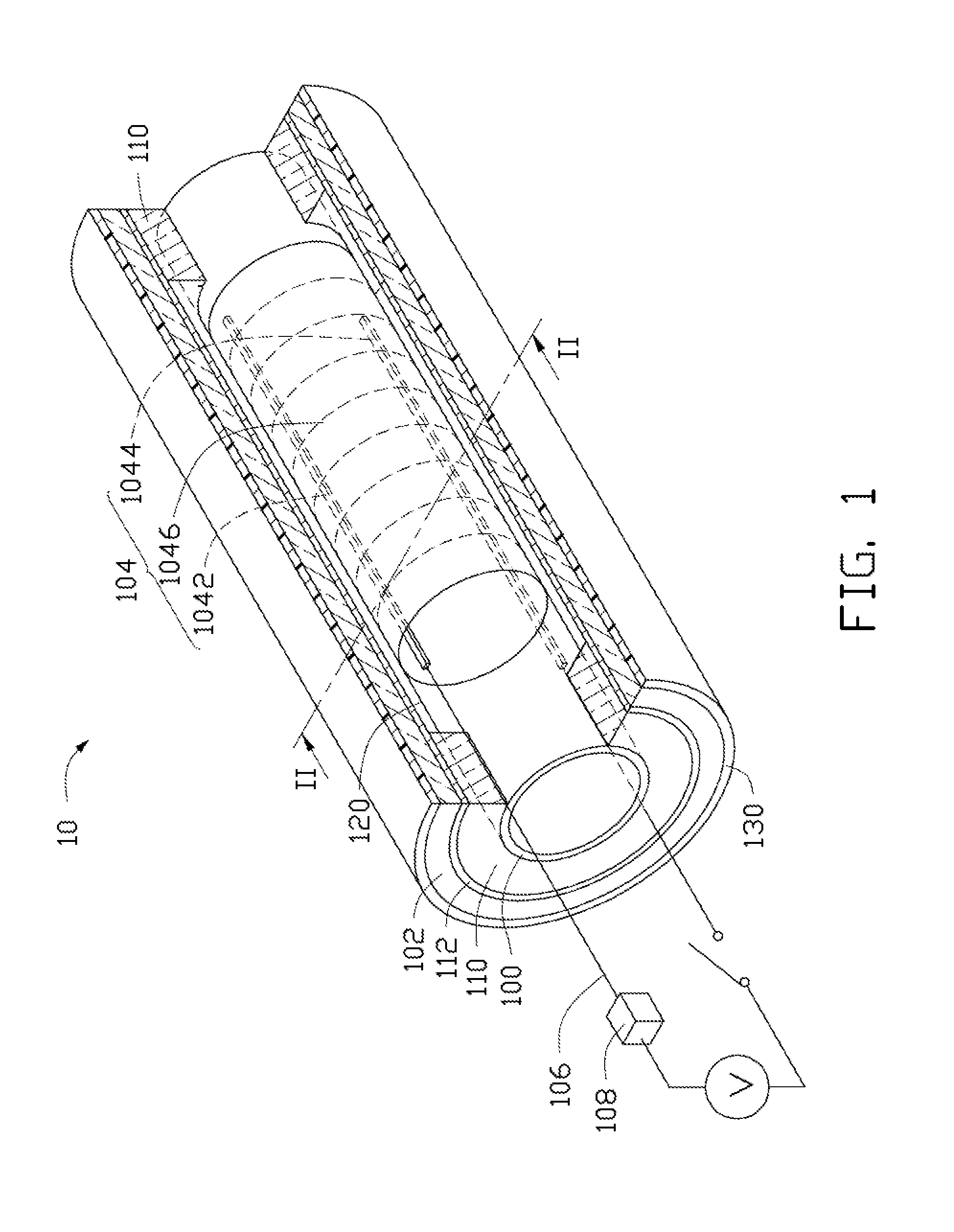
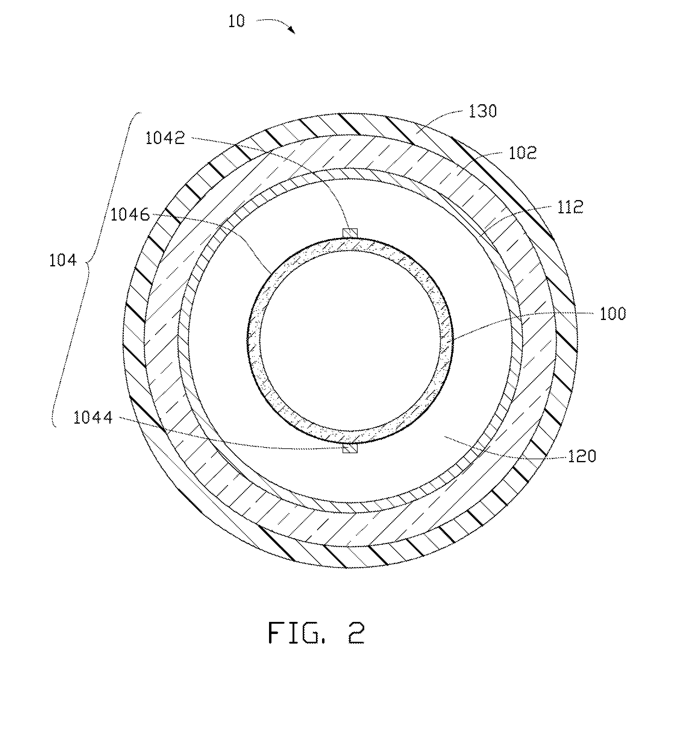
[0018]Referring to FIGS. 1 and 2, a fluid heater 10 of one embodiment is shown. The fluid heater 10 includes an inner pipe 100, an outer pipe 102 surrounding the inner pipe 100, two sealed elements 110 located on an outer surface of the inner pipe 100, and a heating module 104 located between the inner pipe 100 and the outer pipe 102. The two sealed elements 110 contact two ends of the outer pipe 102, and are located between the inner pipe 100 and the outer pipe 102. The inner pipe 100, the two sealed elements 110, and the outer pipe 102 cooperatively define a sealed room 120.

[0019]The inner pipe 100 encircles and is located on an outer surface o...


PUM


Abstract

A fluid heater includes an inner pipe and an outer pipe. The outer pipe surrounds the periphery of the inner pipe and is located separate from the inner pipe. The fluid heater further includes two sealed elements located apart from each other and between the inner pipe and the outer pipe. The inner pipe, the outer pipe and the two sealed elements define a sealed room. A heating module is located in the sealed room.

Description

RELATED APPLICATIONS[0001]This application claims all benefits accruing under 35 U.S.C. §119 from China Patent Application No. 201010111807.4, filed on Feb. 8, 2010 in the China Intellectual Property Office, the contents of which are hereby incorporated by reference. The application is also related to copending application entitled, “HEATING PIPE”, filed ______ (Atty. Docket No. US30479).BACKGROUND[0002]1. Technical Field[0003]The present disclosure generally relates to a fluid heater.[0004]2. Description of Related Art[0005]In everyday life, industry, or science research, a heating fluid is needed. Heaters for fluid are often used to heat fluid, such as liquid or gas.[0006]A conventional fluid heater includes an inner pipe and an outer pipe surrounding the inner pipe. The inner pipe and the outer pipe define a cavity. Heating wires are located in the inner pipe. In use, the conventional fluid heater is fixed at one end of a fluid pipe. The fluid flowing in the fluid pipe will be gu...

Claims


Application Information

Patent Timeline
IPC IPC(8): F24H1/12B82Y99/00
CPCA61M5/44A61M2205/3633A61M2205/3653H05B3/42F24D2200/08F24H1/162B82Y30/00
Inventor WANG, JIA-PINGXIE, RUIJIANG, KAI-LIFAN, SHOU-SHAN
Owner TSINGHUA UNIV
Why Eureka
Try Eureka