Slipform Paving Machine With Adjustable Length Tractor Frame

a tractor frame and slipform technology, applied in the direction of paving reinforcements, roads, construction, etc., can solve the problems of increasing the time, complexity and difficulty of changing the width of the tractor frame, reducing so as to save the downtime of the machine and enhance the efficiency of the paver. , the effect of fast and effectiv

Active Publication Date: 2011-08-11
GUNTERT & ZIMMERMAN CONSTR DIV
View PDF11 Cites 33 Cited by
  • Summary
  • Abstract
  • Description
  • Claims
  • Application Information

AI Technical Summary

Benefits of technology

[0008]It is a principal object of the present invention to streamline and speed up changing the width of the tractor frame of a slipform paving machine by increasing the range over which the bolsters of the machine can be extended by means of moving the telescoping support beams in or out in a simple, effective and inexpensive manner to thereby reduce the frequency with which bolt-in, fixed support beam extensions must be installed.
[0012]As is described in detail below, this change in the length of the tractor frame is preferably performed in accordance with the present invention by moving one or both of the bolsters relative to the center module with the crawlers of the respective bolsters. This change is fast and effective, saves machine down-times during the change, and thereby enhances the efficiency of the paver.

Problems solved by technology

However, the length of the center module limits the distance over which the support beams can be extended away from the center module because a substantial portion of the support beams, typically about three to four feet, must remain secured inside the center module so that the support beams are firmly supported by the center module.
While it is relatively simple and not very time-consuming to change the length of the tractor frame by moving the telescoping support beams in or out, installing bolt-in, fixed support beam extensions to increase the length of the frame past its maximum width attainable with the telescopic support beams significantly increases the time, complexity and difficulty of changing the width of the tractor frame.
The drawback of such arrangements is that two-stage, hydraulic, double telescopic extenders are complicated, costly to build and maintain, and are difficult to keep from deflecting under vertical loads, thereby reducing the effective paving capability of the paver.

Method used


Image

  • Slipform Paving Machine With Adjustable Length Tractor Frame
  • Slipform Paving Machine With Adjustable Length Tractor Frame
  • Slipform Paving Machine With Adjustable Length Tractor Frame

Examples


Embodiment Construction

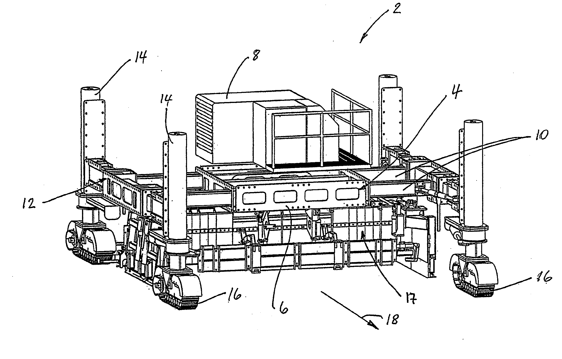
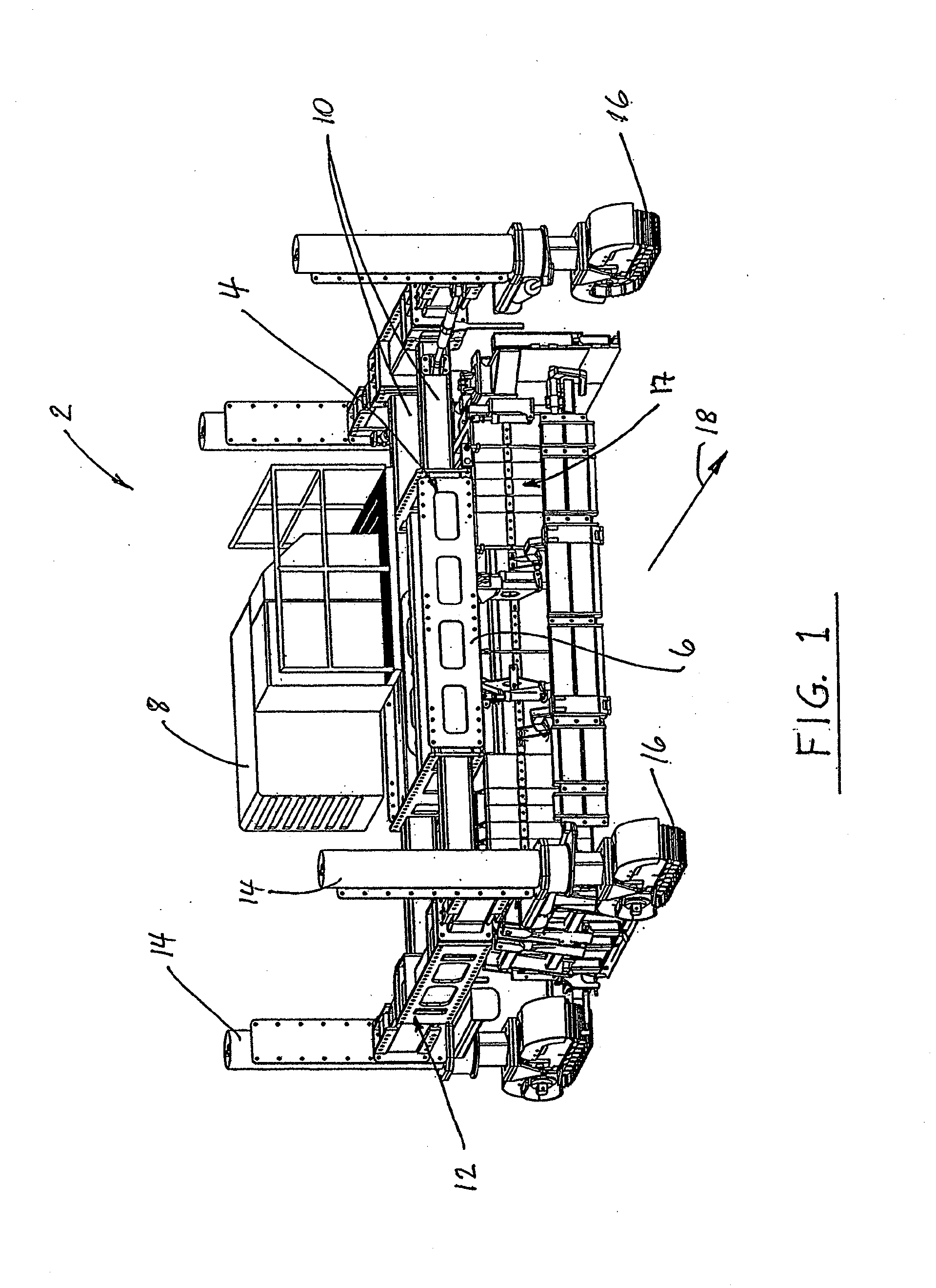
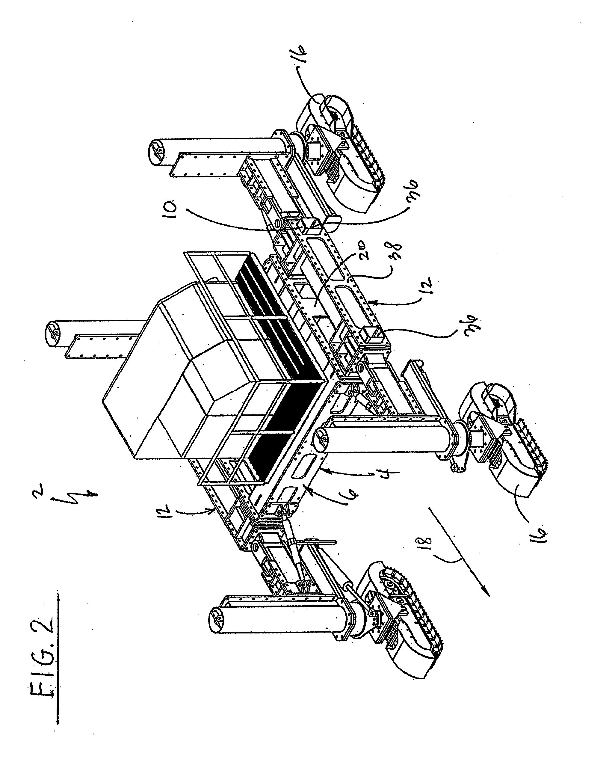
[0025]Referring initially to FIG. 1, a concrete slipform paving machine 2 has a main tractor frame 4 defined by a center module or platform 6 that carries the diesel engine powered power unit 8 of the paving machine and from which extendable or telescoping support beams 10 extend outwardly in a lateral direction. Bolsters 12 are secured to the respective outboard ends of the support beams. Upright jacking columns 14 are mounted at front and aft ends of the bolsters, and crawlers 16 are conventionally secured to the lower ends of the jacking columns. The jacking columns are preferably hydraulically powered for raising and lowering of the paving machine relative to the crawlers on the ground. The crawlers are mounted to the lower ends of the jacking columns, and they are rotatable relative to the jacking columns about vertical axes, an arrangement that is known in the art. The crawlers support the entire machine and move it over the ground.

[0026]The respective bolsters can be moved in...


PUM


Abstract

A paving machine that moves in a travel direction and spreads, levels and finishes concrete into a form having a generally upwardly exposed, finished concrete surface that terminates in lateral sides. The paving machine has a main frame with first and second bolsters arranged at opposite ends of the main frame. Each set of bolsters has two hydraulic jacking columns used to raise and lower the machine frame. Crawlers attached to the bottom of the jacking columns engage the ground and move the paving machine in the travel direction. A pair of support beams is attached to the inner surface of each bolster and supported in passageways of a center module of the tractor frame. To extend the maximum width of the paving machine without having to extensively disassemble it, the free ends of the support beams extend beyond outer sides of the bolsters when the distance between the inner sides of the bolsters is at its minimum. This paving machine width adjustment can be performed in the field by moving the bolsters and the support beams attached to them inwardly or outwardly with the crawlers of the paving machine. Also provided is a laterally extendable / retractable cross beam for movably supporting a dowel bar inserter kit on the paving machine.

Description

BACKGROUND OF THE INVENTION[0001]The present invention concerns concrete slipform paving machines that have a propelling unit or tractor from which a paying kit is suspended with which a layer of concrete is shaped and finished over the underlying ground as the propelling unit travels along a road or airfield alignment. The tractor of a concrete slipform paver has a rectilinear frame which straddles the concrete roadway or airfield pavement section that is being paved. The frame is propelled and supported on either end by crawler tracks mounted on side bolsters. These side bolsters each typically have two hydraulic supporting jacking columns, each of which connects to a crawler track, that allow the tractor frame elevation to be manually or automatically varied relative to the ground. The frame, and in particular a center module thereof, supports a diesel engine-driven hydraulic power unit which supplies power to the tractor and the paving kit.[0002]The paving kit is conventionally ...

Claims


Application Information

Patent Timeline
Patent Type & Authority Applications(United States)
IPC IPC(8): E01C19/12
CPCE01C19/4853
Inventor GUNTERT, JR., RONALD M.DAHLINGER, GERALD L.DELEV, IOVTCHO MITEVMICKELSON, STEVEN DOUGLAS
Owner GUNTERT & ZIMMERMAN CONSTR DIV
Why Eureka
Try Eureka