

Method and System for Detecting Conflicts between Outage Requests and Power Supply Guarantee Requests in a Power Grid
- Summary
- Abstract
- Description
- Claims
- Application Information
AI Technical Summary
Benefits of technology
Problems solved by technology
Method used
Image

Examples
first embodiment
[0029]Referring to FIG. 3, the invention provides a method of detecting conflicts between PSGRs and ORs in a power grid. FIG. 3 illustrates a process flow 300 used by invention, comprising the following steps:
[0030]Step 310: receiving an OR device set and a PSGR device set.
[0031]Step 320: using geographical information to determine an outage device set further including accompanying outage devices.
[0032]Step 330: using topology information of power grid to determine the outage scale or scope.
[0033]Step 340: detecting if a conflict exists.
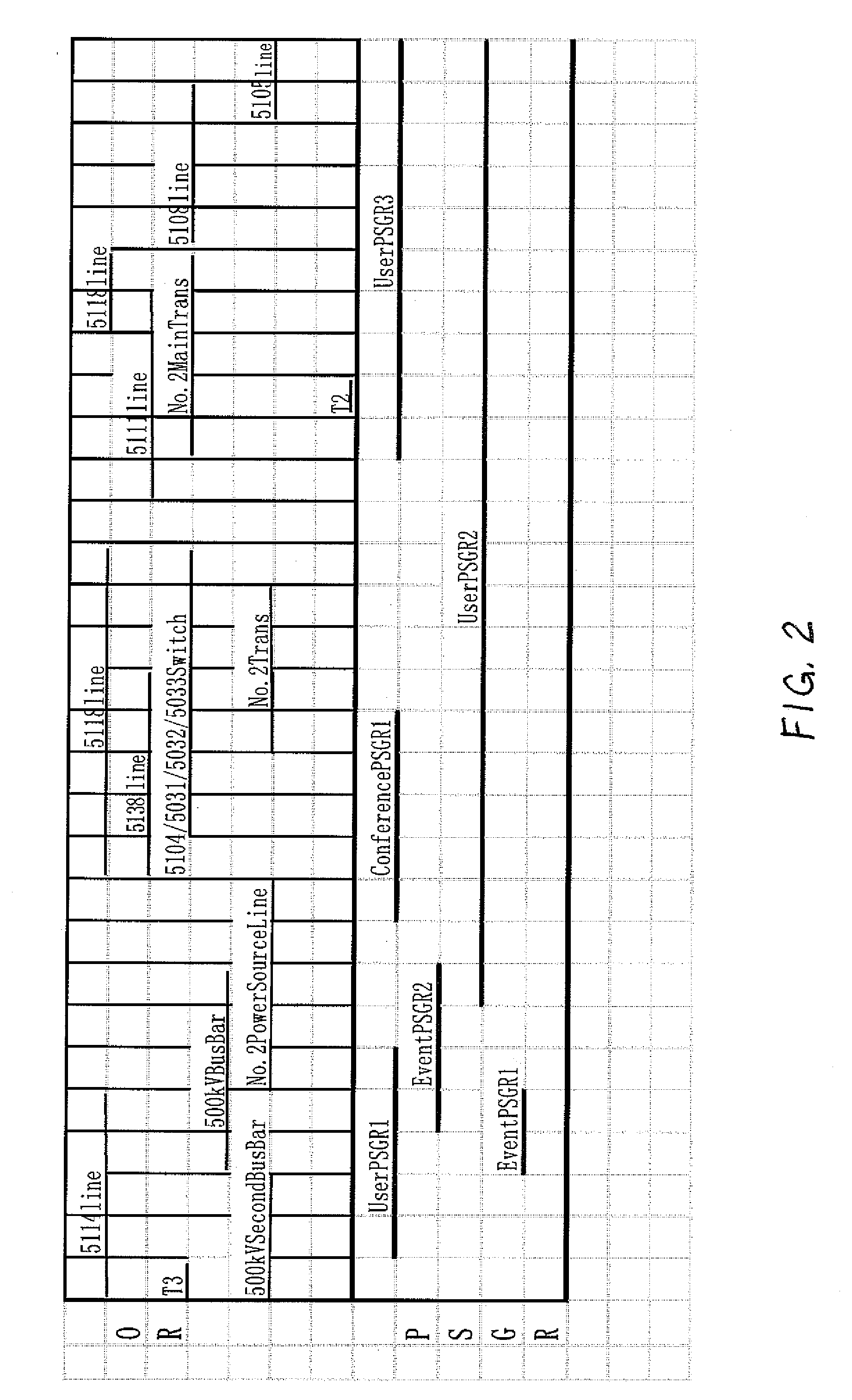
[0034]Note that the process flow 300 should be performed at certain points in time, including the power supply guarantee start timing, the power supply guarantee end timing, outage start timing and outage end timing located between power supply guarantee start timing and power supply guarantee end timing. In this manner, taking the PSGR, “user PSGR 1” in FIG. 2, as an example, process flow 300 is preferably performed at the following time points: st...
second embodiment
[0076]Hereinafter referring to FIG. 6, a process flow 600 used by invention is illustrated. The process flow 600 in FIG. 6 is substantially the same as process flow 300 in FIG. 3, and processing in steps 610, 620, 640 in process flow 600 is the same as that in steps 310, 320, 340 in process flow 300 completely. Performing timings of process flow 600 are also the same as those of process flow 300. The difference between process flow 600 and process flow 300 is that process flow 600 further comprises step 650, and except the first run, step 630 in process flow 600 is different from step 330 in process flow 300.
[0077]Hereinafter, FIG. 7 is referenced to explain the process flow 600 in FIG. 6. Relative to FIG. 4, FIG. 7 adds a main transformer T2, bus bar B4 and switches S5 and S6, wherein the upside of main transformer T2 is also connected to a power source line. The remaining portion of the power grid example in FIG. 7 is the same as the power grid example in FIG. 4. Process flow 600 ...
PUM
 Abstract
Description
Claims
Application Information