
Handling device and method

a technology of handling device and handling device, which is applied in the direction of wheel mounting apparatus, instruments, and static/dynamic balance measurement, etc., can solve the problems of not being suitable for use inside narrow mining tunnels, difficult to transport tyres to, align tyres with, and heavy lifting equipment such as hoists or cranes

Inactive Publication Date: 2011-08-18
JUSTOY PTY LTD
View PDF10 Cites 15 Cited by
  • Summary
  • Abstract
  • Description
  • Claims
  • Application Information

AI Technical Summary

Benefits of technology

The present invention provides an apparatus and method for transporting and installing or removing an article, such as a wheel or tyre, in a confined space. The apparatus includes a frame and an article support that can be moved relative to the frame between a retracted position and an extended position. The article support can be positioned in the extended position to engage the article with a receiving member. The apparatus can also include stabilizing means to engage the substrate surface and stabilize the frame when the article support is moved and positioned in the extended position. The apparatus can be controlled using hydraulics, electric motors, or other like machinery. The invention provides a compact and efficient solution for transporting and installing or removing articles in restricted areas.

Problems solved by technology

Replacing these oversized spare parts can be an onerous task requiring multiple workmen and in most cases the assistance of bulky machinery that is often difficult to manoeuvre.
If one considers the procedure involved with changing the tyre of a mining vehicle, there are several difficulties to overcome.
At first instance, the sheer size of the tyre or wheel can make it almost impossible to transport the tyre to, and align it with, a compatible vehicle.
Common lifting equipment such hoists or cranes are bulky and not suitable for use inside narrow mining tunnels.
Furthermore such lifting equipment is typically not capable of transporting the tyre in a stable state when travelling over rough uneven surfaces, as is common in the mines.
The tyre may often shift or swing around, that may lead to damage of the new tyre or injuries to nearby persons.

Method used


Image

  • Handling device and method
  • Handling device and method
  • Handling device and method

Examples


Embodiment Construction

[0054]Throughout the drawings, like numerals will be used to identify similar features, except where expressly otherwise indicated.

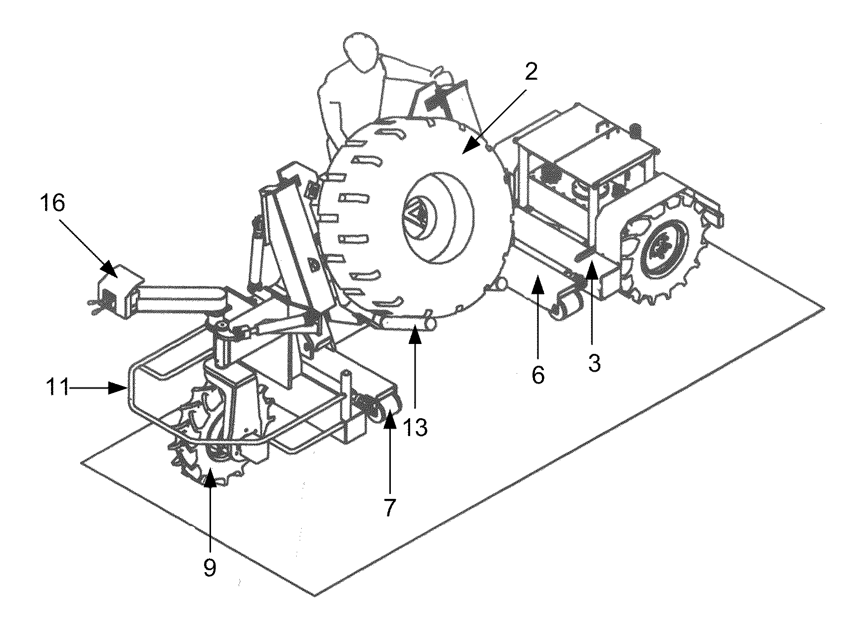
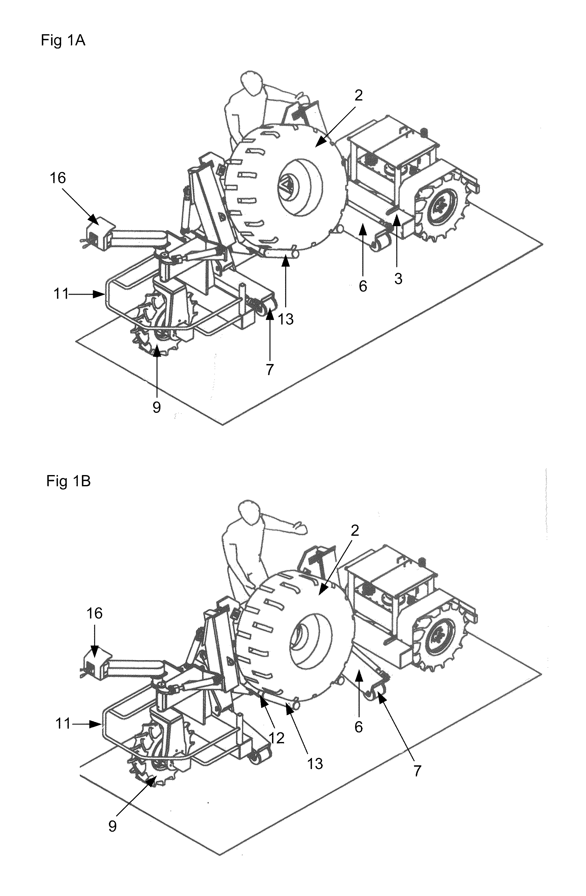
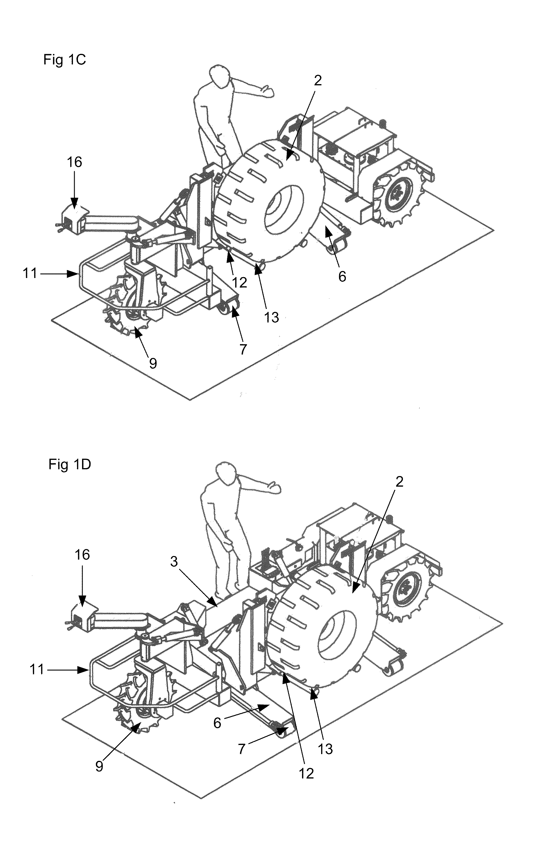
[0055]The apparatus of the present invention, generally designated by the numeral (1), is used to transport an article (2) and manoeuvre it into position. Throughout the drawings, the article (2) is exemplified as a wheel, which may typically be transported on the apparatus (1) through a confined space such as a mine shaft, to replace a wheel on a mining machine which is located within the mine shaft. It will therefore be appreciated that such a wheel changing operation must be conducted within a confined space. It will also be appreciated that such mining equipment wheels are extremely heavy and large. The apparatus of the present invention takes these considerations into account to manoeuvre such a large heavy article as a wheel into position and appropriately manoeuvre the wheel into location on a wheel hub of a stranded mine vehicle.

[0056]FIG. 1 illu...


PUM

PropertyMeasurementUnit
movementaaaaaaaaaa
sizeaaaaaaaaaa
central structureaaaaaaaaaa

Abstract

An apparatus (1) for transporting an article (2). The apparatus (1) includes a frame (3) and an article support (4) operatively coupled to the frame (3). The article support (4) is movable relative to the frame (3) such that the apparatus (1) provides a first configuration for retaining the article (2) and a second configuration for receiving or unloading the article (2). The apparatus (1) includes a plurality of wheels (9) for movement over a substrate surface, and, a stabilising means (6) to engage the substrate surface and stabilise the frame (3) when the apparatus (1) is in the extended position. In use, the apparatus (1) may be used to support a wheel, tyre or other vehicular component (2) during installation, for example, in a confined space such as a mine.

Description

BACKGROUND OF THE INVENTION[0001]The present invention relates to an article handling apparatus and method. In particular, the present invention relates to an apparatus and method for transporting an article, such as, but not limited to a wheel or other spare part, and for handling the article in a replacement or installation process. The invention has particular application in the mining and earthmoving fields.DESCRIPTION OF THE PRIOR ART[0002]The reference in this specification to any prior publication (or information derived from it), or to any matter which is known, is not, and should not be taken as, an acknowledgement or admission or any form of suggestion that that prior publication (or information derived from it) or known matter forms part of the common general knowledge in the field of endeavour to which this specification relates.[0003]Mining is centred on the extraction of resources and minerals from the earth. From a productivity point of view, mining typically requires...

Claims


Application Information

Patent Timeline
Patent Type & Authority Applications(United States)
IPC IPC(8): B23P19/00B60P1/04B60B29/00B60P1/32B60B30/00B23Q1/25B23P11/00
CPCB60B29/00Y10T29/49819Y10T29/49826B60B30/00
Inventor HEDLEY, ROBERT IAN
Owner JUSTOY PTY LTD
Learn More