Visible-light communication system system and method

a communication system and light technology, applied in the field of visible light communication system and method, can solve the problems of difficult generation of deterioration of transmission quality according to the reduction of luminescence amount, and achieve the effect of effectively reducing deterioration of transmission quality, and removing the propagation path characteristic from the optical signal

Active Publication Date: 2011-08-18
SAMSUNG ELECTRONICS CO LTD
View PDF11 Cites 68 Cited by
  • Summary
  • Abstract
  • Description
  • Claims
  • Application Information

AI Technical Summary

Benefits of technology

[0013]The transmission device further includes a chromaticity coordinate modulator to match the transmission data to a predetermined chromaticity point arranged on chromaticity coordinates. The luminescence calculator calculates a luminescence amount of each of the light emitting units so that a color corresponding to the chromaticity point matched with the transmission data by the chromaticity coordinate modulator is radiated. The propagation path compensation unit compensates the corresponding optical signal for the propagation path based on the channel matrix estimated by the channel estimation unit when the optical signal corresponding to the chromaticity point is received in each of the light receiving units. The data demodulator detects the chromaticity point on the chromaticity coordinates and demodulates the transmission data based on the signal output from the propagation path compensation unit. As such, in the visible light communication system, the transmission data is matched to the chromaticity point on the chromaticity coordinates by the chromaticity coordinate modulator and is modulated. That is, the transmission data is modulated by a ratio of each color. Therefore, even if the luminescence amount is reduced in the propagation path, information included in the optical signal is not lost, so that it is difficult to generate the deterioration of the transmission quality according to the luminescence amount reduction.
[0014]The preamble signal includes a synchronization code component used for a timing synchronization and a channel estimation code component which is used for a channel estimation. The preamble signal generator generates the preamble signal corresponding to each of the light emitting units. The light emission controller controls each of the light emitting units based on the corresponding preamble signal. The synchronization code component of the preamble signal corresponding to one light emitting unit and the synchronization code component of the preamble signal corresponding to another light emitting unit have are identical. The channel estimation code component of the preamble signal corresponding to one light emitting unit and the channel estimation code component of the preamble signal corresponding to another light emitting unit are orthogonal with each other. By using the aforementioned preamble signal, it is possible to detect the synchronization timing from the synchronization code component and detect a position and existence of a signal continuously included in the synchronization code.
[0016]Further, the propagation path compensation unit applies a weight matrix (W) calculated based on the channel matrix (H) to the optical signal and compensates the corresponding signal for the propagation path. For example, the weight matrix W is W=(H×HH)−1×HH. The method has a comparatively low calculation load, so that it is possible to execute the high-rate compensation for the propagation path. Further, each of the components of the channel matrix H in the visible light communication is a real number, so that the load is smaller and thus the high-rate compensation can be realized.
[0019]In the visible light communication system and method, the preamble signal used for the estimation of the channel matrix is added to the optical signal and transmitted. Further, the propagation path compensation is executed to the optical signal based on the channel estimation estimated using the preamble signal. The channel matrix represents a propagation characteristic of the light propagation path. Therefore, it is possible to remove the propagation path characteristic from the optical signal by using the channel matrix. Therefore, it is possible to remove the propagation path characteristic from the optical signal by using a Zero Focusing (ZF) method, effectively reducing deterioration of the transmission quality.
[0020]Accordingly, the visible light communication system and method of the present invention can reduce the influence of the propagation characteristic on the light propagation path and improve the transmission quality.

Problems solved by technology

Therefore, even if the luminescence amount is reduced in the propagation path, information included in the optical signal is not lost, so that it is difficult to generate the deterioration of the transmission quality according to the luminescence amount reduction.

Method used


Image

  • Visible-light communication system system and method
  • Visible-light communication system system and method
  • Visible-light communication system system and method

Examples


Embodiment Construction

[0032]Hereinafter, exemplary embodiments of the present invention will be described with reference to the accompanying drawings. In the following description, the same elements will be designated by the same reference numerals although they are shown in different drawings, and the repeated description for the same reference numeral will be omitted.

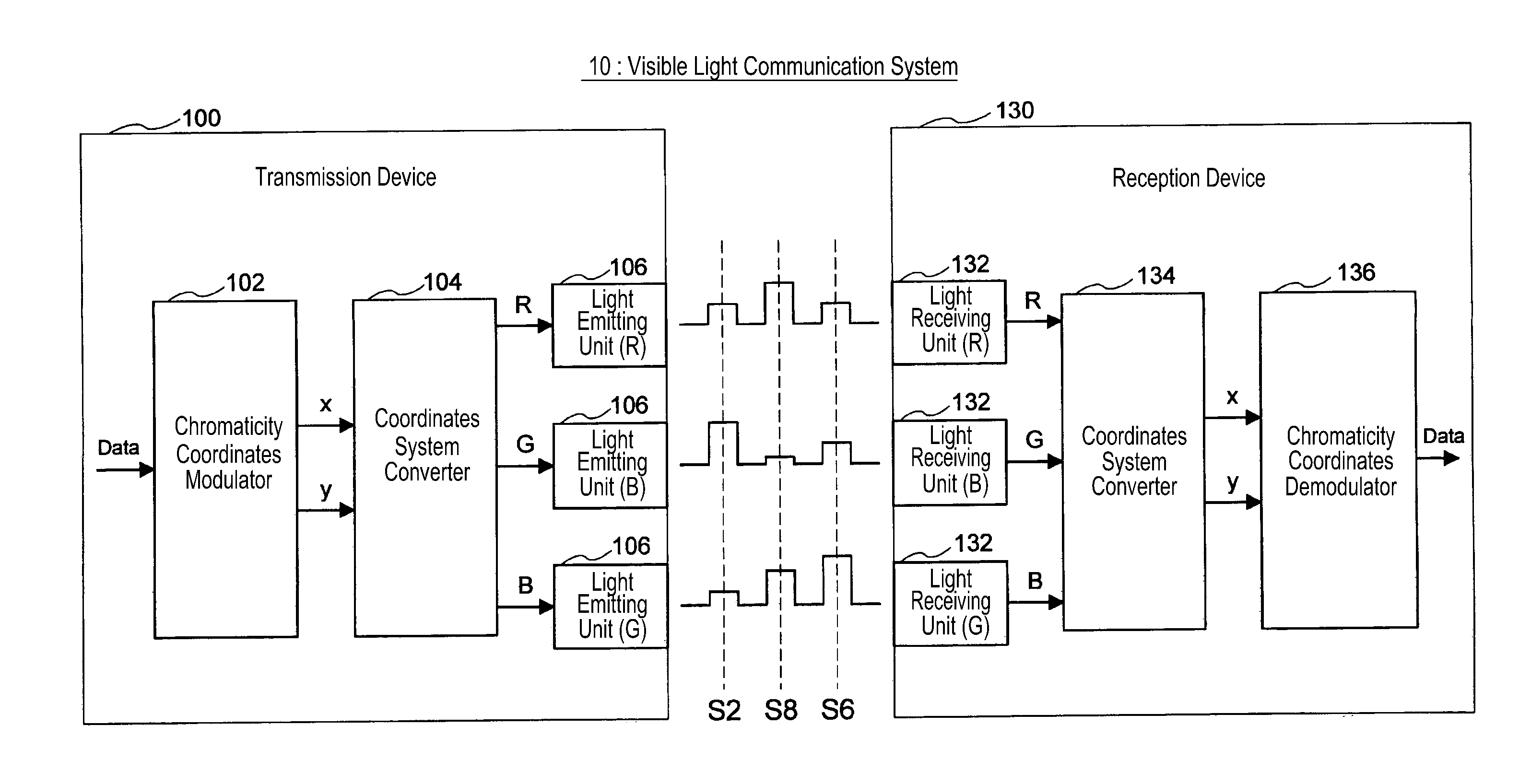
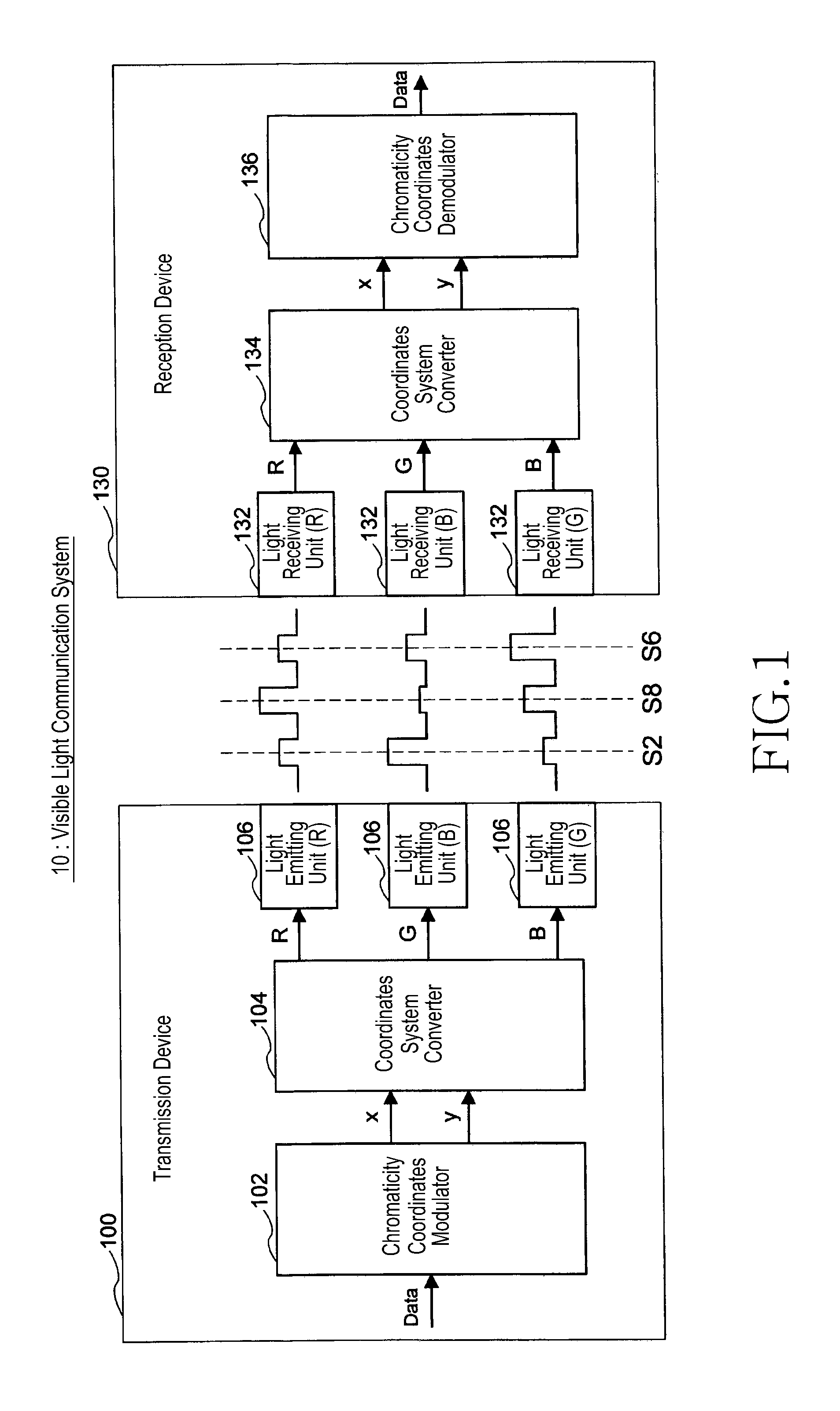
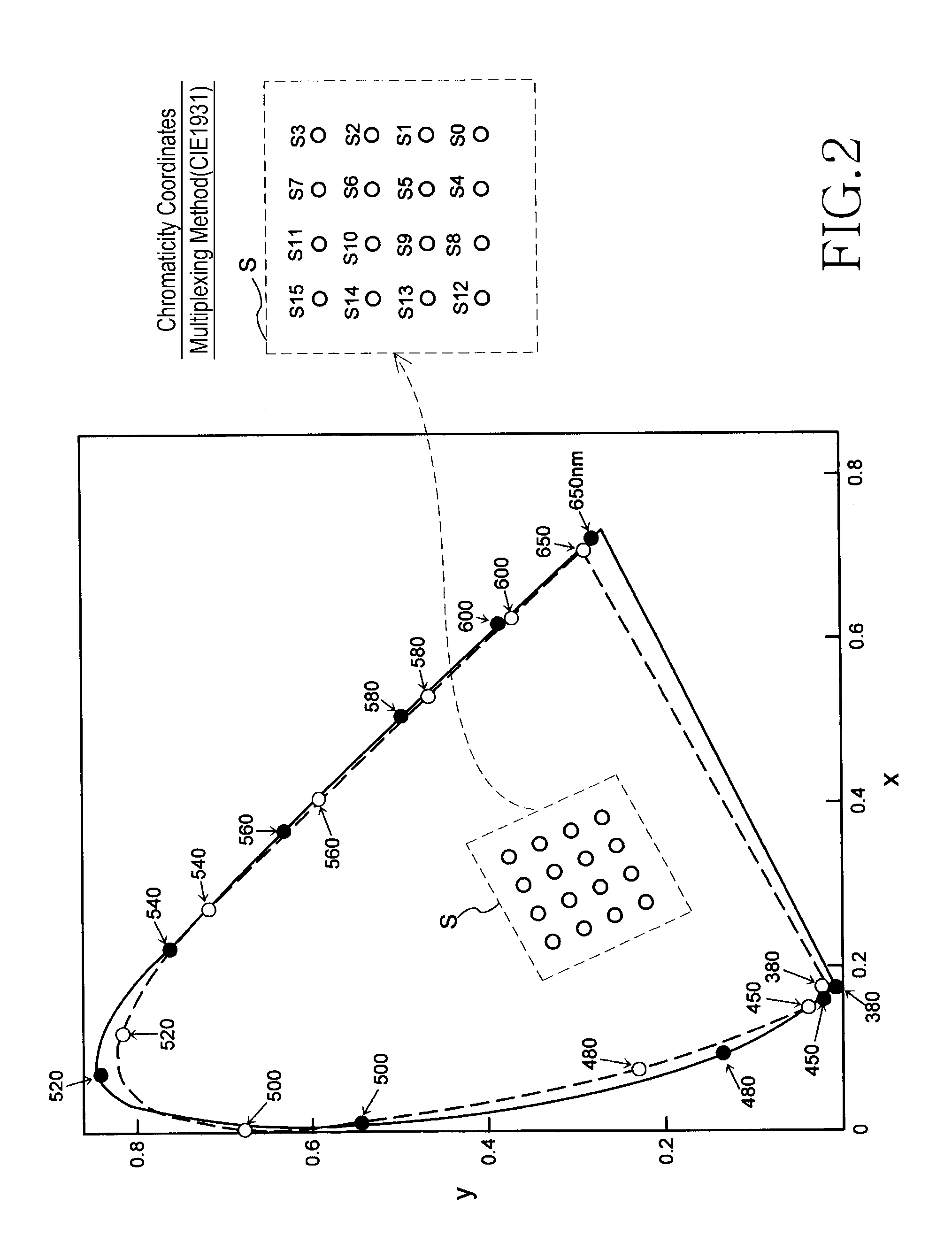
[0033]Here, the flow of the description of an embodiment of the present invention to be described below will be briefly described. First, a visible light communication method according to a chromaticity coordinates multiplexing scheme will be described with reference to FIGS. 1 to 4. In the description, a technical problem of a visible light communication system 10 based on the conventional chromaticity coordinates multiplexing scheme will be described. Then, a construction and an effect of a visible light communication system 20 according to an embodiment of the present invention will be described in detail with reference to FIGS. 5 to 10...


PUM


Abstract

Disclosed is a visible light communication system including a transmission device, including multiple light emitting units emitting light of different colors and mapping transmission data to a chromaticity point, calculating luminescence of each of the light emitting units, generating a preamble signal for channel matrix estimation, and emitting light based on the preamble signal and calculated luminescence amount. A reception device of the visible light communication system includes multiple light receiving units and estimates a channel matrix based on a corresponding optical signal when an optical signal corresponding to the preamble signal is received in each light receiving unit, compensates the optical signal corresponding to the chromaticity point for a propagation path based on the estimated channel matrix, detects a chromaticity point on the chromaticity coordinates based on a signal after the propagation path compensation, and demodulates the transmission data.

Description

PRIORITY[0001]This application claims priority under 35 U.S.C. §119(a) to Patent Application No. 268490 / 2008 filed in the Japanese Intellectual Property Office on Oct. 17, 2008, and to PCT / KR2009 / 005964 filed Oct. 16, 2009, the content of each which is incorporated herein by reference.BACKGROUND OF THE INVENTION[0002]1. Field of the Invention[0003]The present invention relates to a visible light communication system and method for use thereof, and more particularly to an improved visible light communication system and method for reducing influence of a propagation characteristic on a light propagation path and improving transmission quality.[0004]2. Description of the Related Art[0005]Recent light communication technology uses light in a visible region, especially for light emitting devices such as a Light Emitting Diode (LED) to achieve a more convenient and higher-rate data communication using an infrastructure of a lighting device installed inside or outside of a building.[0006]C...

Claims


Application Information

Patent Timeline
Patent Type & Authority Applications(United States)
IPC IPC(8): H04B10/00H04B10/11H01L31/0232H01L33/00H04B10/116H04B10/524H04B10/58H04J14/00H04J14/02
CPCH04B10/116H04B10/1149H04B10/00H04B10/50H04B10/60
Inventor YOKOI, ATSUYA
Owner SAMSUNG ELECTRONICS CO LTD
Why Eureka
Try Eureka