Network system, optical line terminating apparatus, and optical network apparatus

a network system and optical line technology, applied in the field of optical communication systems, can solve the problems of significant limit in transmission speed and transmission distance deterioration of receive sensitivity, etc., and achieve the effects of simple and inexpensive, excellent transmission quality, and low power consumption

Inactive Publication Date: 2009-07-02
HITACHI LTD
View PDF5 Cites 10 Cited by
  • Summary
  • Abstract
  • Description
  • Claims
  • Application Information

AI Technical Summary

Benefits of technology

[0009]According to the present invention, an optical communication system for access, which is excellent in the transmission quality, of low power consumption, simple and inexpensive, c

Problems solved by technology

However, in an optical transmission system having its bit rate of 10 Gbps, transmission speed and transmission distance are significantly limited by the phenomena, such as deterioration of receive sensitivity, and wavelength dispersion of an optical fiber due to its high-speed.
The deterioration of receive sensitivity is caused by the deterioration of S/N ratio due to an increase of noise which follows its higher-speed.
However, when an optical amplifier with a large output is adopted, it causes a serious problem in that an optical surge, that is, an overshoot caused by a high gain optical amplifier can destroy a receiver.
As a result, a waveform of an optical signal causes a distortion after passing through a fiber.
However, a dispersion compensator is very expensive to be used in the PON system, therefore it is very difficult to be adopted really.
The chirp causes a group delay in accordance with a wavelength dispersion value of an optical transmission line, and causes a waveform of an optical signal pulse to be dist

Method used


Image

  • Network system, optical line terminating apparatus, and optical network apparatus
  • Network system, optical line terminating apparatus, and optical network apparatus
  • Network system, optical line terminating apparatus, and optical network apparatus

Examples


Embodiment Construction

[0020]Hereinafter, embodiments of the present invention will be described in detail with reference to accompanying drawings.

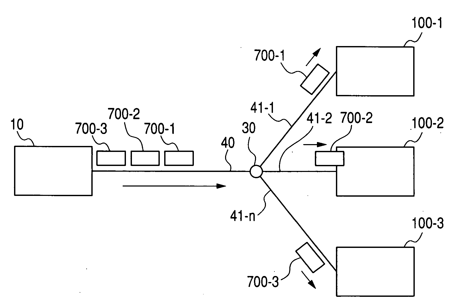
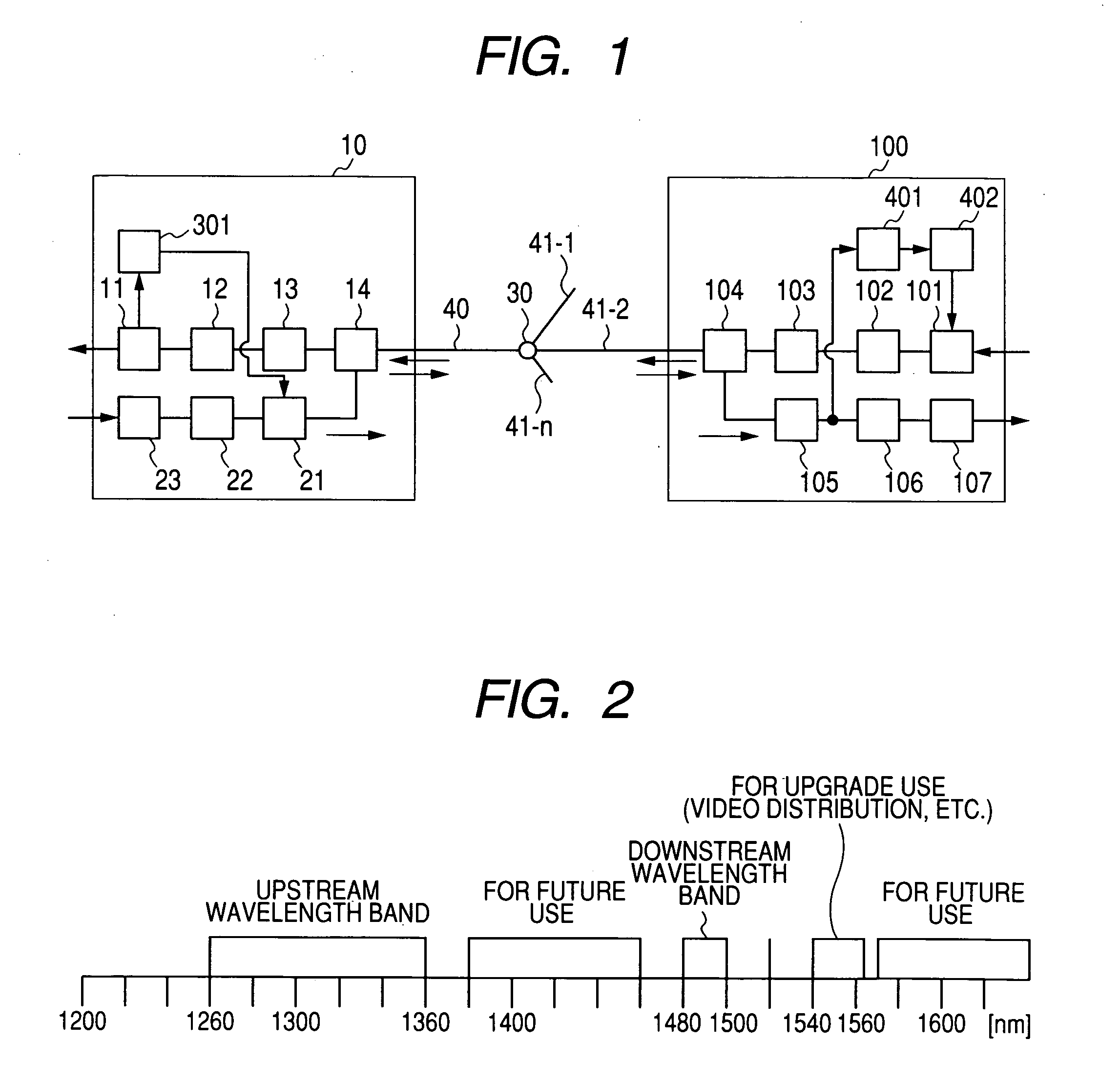
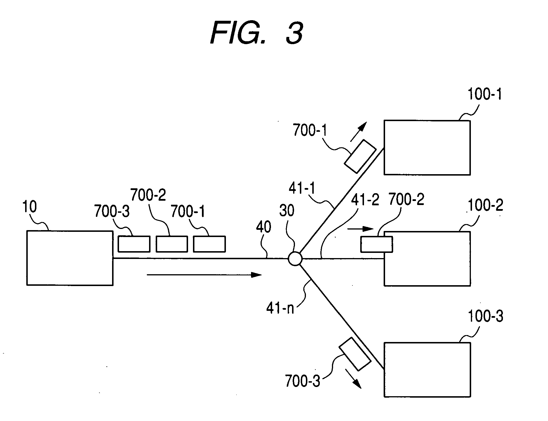
[0021]FIG. 1 shows a structure of the PON system according to the present invention. The PON system includes an optical communication apparatus (OLT) transmitter / receiver 10 which is placed on the side of a central office, and one or more optical communication subscriber apparatus (ONU) transmitters / receivers 100 on the side of users. Those apparatuses are connected together by optical fibers 40 and 41, and an optical splitter 30. The OLT transmitter / receiver 10 includes a WDM 14, an optical receiver 13, a reception analog front end 12, a reception logic module 11, a transmission logic module 23, a transmission analog front end 22, a light source with modulation function 21, and an output power controller 301. The ONU transmitter / receiver 100 includes a WDM 104, an optical receiver 105, a reception analog front end 106, a reception logic module 107, a transmiss...


PUM


Abstract

A general object of the present invention is to provide an optical communication system in which an optical transmission power of an optical communication apparatus is controlled to be a required minimum power that apparatuses of all subscribers in the optical communication system meet a prescribed error rate. An optical line terminating apparatus (OLT) transmits data to multiple optical network apparatuses (ONUs) at an optical intensity calculated based on information acquired from the multiple ONUs, which is related to optical intensities of signals that the multiple ONUs receive from the OLT, the optical intensity being calculated so that a minimum optical intensity of the optical intensities of the signals is greater than a predetermined value.

Description

CLAIM OF PRIORITY[0001]The present application claims priority from Japanese application JP 2007-333446 filed on Dec. 26, 2007, the content of which is hereby incorporated by reference into this application.FIELD OF THE INVENTION[0002]The present invention relates to an optical communication system used for the Passive Optical Network (PON) in which the Time Division Multiple Access (TDMA) and the Wavelength Division Multiple Access (WDMA) are concurrently used, in a signal multiplexing technology when constituting an optical access network.BACKGROUND OF THE INVENTION[0003]As services have been diversified on networks, we have widely used those new services which make use of advantages of networks. A typical example of the movements is a broadcasting and communication converged service, that is, an integrated service of broadcasting, Internet, and telephone (voice communication), which is called a triple-play service. In order to realize the triple-play service, constitution of Fibe...

Claims


Application Information

Patent Timeline
IPC IPC(8): H04J14/00H04B10/27H04B10/00H04B10/07H04B10/272H04B10/293H04B10/40H04B10/50H04B10/564H04B10/572H04B10/60H04J14/02
CPCH04B10/27H04J3/0682H04B10/272
Inventor SUGAWARA, TOSHIKIIKEDA, HIROKIYAJIMA, YUSUKEKAZAWA, TOHRU
Owner HITACHI LTD
Why Eureka
Try Eureka