Optical communication system and optical line terminating apparatus

a communication system and optical line technology, applied in the field of optical communication system and optical line terminating apparatus, can solve the problems of deterioration of receive sensitivity, increase of noise (n) components, and significant limitation of transmission speed and transmission distance, and achieve excellent transmission quality, low trouble rate, and high sensitivity

Inactive Publication Date: 2012-08-21
HITACHI LTD
View PDF14 Cites 13 Cited by
  • Summary
  • Abstract
  • Description
  • Claims
  • Application Information

AI Technical Summary

Benefits of technology

[0010]With respect to the wavelength dispersion, the wavelength dispersion refers to a phenomenon in which lights having different wavelengths propagate inside an optical fiber at different speeds. Since an optical spectrum of an optical signal modulated at a high-speed contains different wavelength components, the components reach a receiver at different times while propagating an optical fiber. As a result, a waveform of an optical signal causes a distortion after passing through a fiber. In order to suppress such waveform deterioration caused by the wavelength dispersion, there is a dispersion compensation technology. In the dispersion compensation technology, an optical element, which has the wavelength dispersion characteristics opposite to that of an optical fiber used in a transmission line, is disposed in an optical transmitter, a receiver, or a relay or the like, thereby aiming to cancel the wavelength dispersion characteristics of the optical fiber and to prevent waveform deterioration from happening. As such an optical element, that is, a dispersion compensator, a device such as a dispersion compensation fiber or an optical fiber grating, which has an opposite dispersion characteristics, has been studied and attempted to be practiced. However, a dispersion compensator is very expensive to be used in the PON system, therefore it is very difficult to be adopted really. As an alternative way of not using a dispersion compensator, use of a low chirp external modulator can be considered. A chirp refers to a minute and dynamic wavelength variation happened when modulating an optical carrier emitted from a communication laser in an optical communications system. The chirp causes a group delay in accordance with a wavelength dispersion value of an optical transmission line, and causes a waveform of an optical signal pulse to be distorted, resulting in the deterioration of transmission quality. When directly modulating a laser beam for a wavelength of, for example, 1490 nm or more which is used in the PON system, it is difficult to realize 20 km of transmission distance due to the influences of the chirp and the dispersion. Thus, it is thought that a way of adopting an EA (Electro-Absorption) modulator which uses the electro-absorption effect of a semiconductor is promising in this case. The reason is as follows: since the EA uses a semiconductor material, the EA is easy to be integrated with an external modulator and a laser together, which can reduce a cost up in comparison with a modulator used an optical crystal having an electro-optical effect, such as LiNbO3. In fact, using such a modulator makes more expensive than a way of directly modulating a laser beam; however, the cost up factor is not a serious one, because, in the PON system, multiple subscribers share the equipment of the central office and the cost for the equipment is divided by the number of the subscribers.
[0012]It is an object of the invention is to provide an optical communication system using an abnormal light cut-off system and an optical line terminating apparatus, in which even when a high power light is inputted from an optical fiber connected to a user side apparatus by a malicious user or an accident, a trouble rate is low, the abnormal light is cut off at high sensitivity, and security is high.
[0039]According to the invention, it becomes possible to provide the optical communication system using the abnormal light cut-off system and the optical line terminating apparatus, in which the transmission quality is excellent, the trouble rate is low, the abnormal light is cut off at high sensitivity, and the security is high.

Problems solved by technology

In an FTTH system having its bit rate of, for example, 10 Gbps, it is conceivable that transmission speed and transmission distance are significantly limited by the phenomena, such as deterioration of receive sensitivity and wavelength dispersion of an optical fiber, due to speeding up.
With respect to the deterioration of receive sensitivity, it is supposed that a noise (N) component increases due to the speeding up, and the deterioration of receive sensitivity is caused by the deterioration of S / N ratio of a receiver output signal.
However, when the optical amplifier with a large output is used, there arises a serious problem that an optical surge, that is, an overshoot of an optical signal caused by the high gain optical amplifier destroys a receiver.

Method used


Image

  • Optical communication system and optical line terminating apparatus
  • Optical communication system and optical line terminating apparatus
  • Optical communication system and optical line terminating apparatus

Examples


Embodiment Construction

[0061]Hereinafter, embodiments of the invention will be described in detail with reference to the drawings.

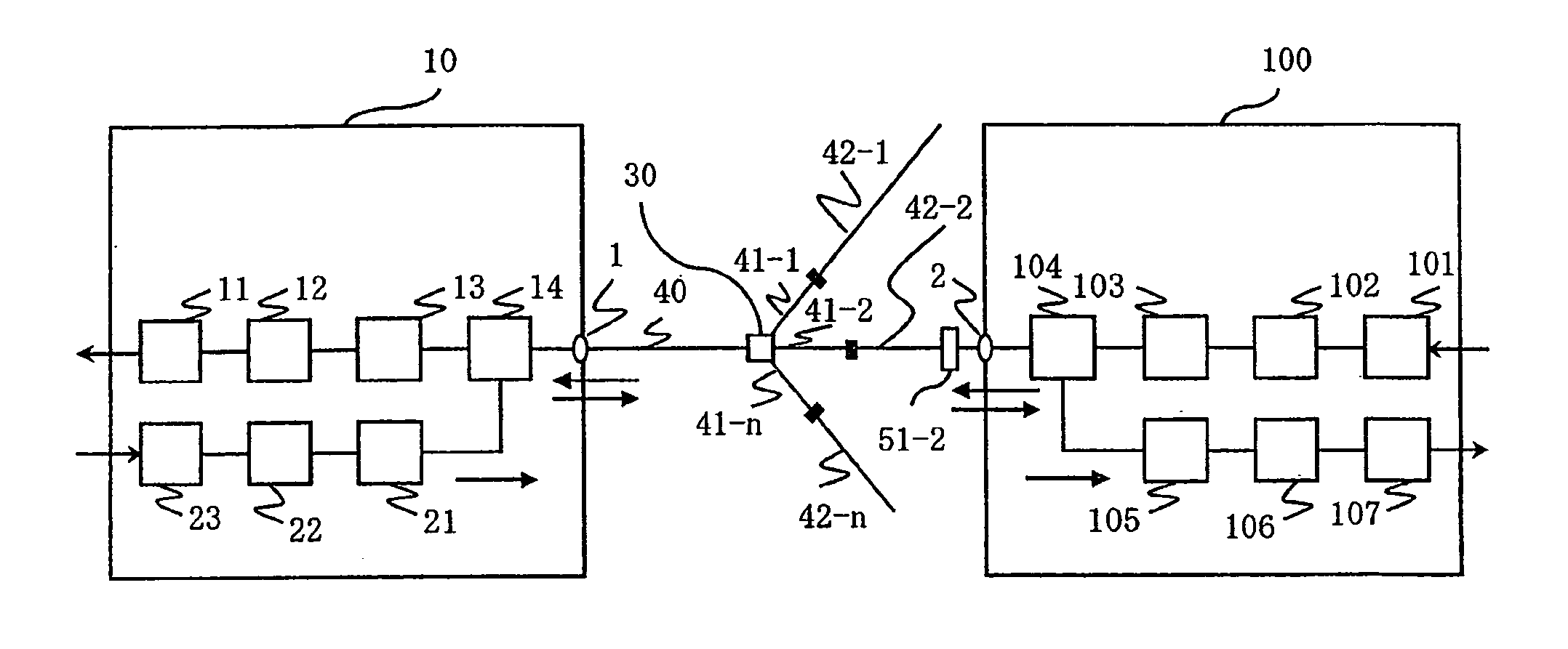
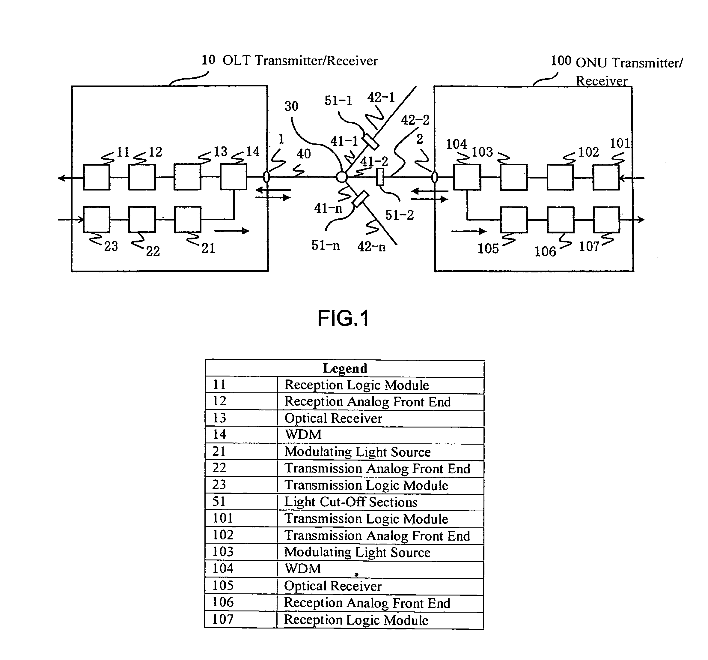
[0062]FIG. 1 is a structural view of a PON system according to an embodiment.

[0063]The PON system includes an optical communication apparatus (OLT) transceiver / receiver 10 placed on the side of a central office, and one or more user side optical communication subscriber apparatus (ONU) transmitter / receiver 100, and those apparatuses are connected together via an optical line terminating apparatus side optical fiber 40, an optical branching section 30, an optical branching section side optical fiber 41, a light cut-off section 51, and an optical network apparatus side optical fiber 42. The OLT transmitter / receiver 10 and the optical line terminating apparatus side optical fiber 40 are coupled by an optical connector 1. The ONU transmitter / receiver 100 and the optical network apparatus side optical fiber 42 are coupled by an optical connector 2. The OLT transmitter / receiver 10 in...


PUM


Abstract

There is provided an abnormal light cut-off system in which even when a high power light is inputted from an optical fiber connected to a user side apparatus by a malicious user or an accident, a trouble rate is low, the abnormal light is cut off at high sensitivity, and security is high. In a network system in which an optical line terminating apparatus and plural optical network apparatuses are connected together via plural optical connection sections and an optical branching section, the optical branching section includes one optical line terminating apparatus side port and plural optical network apparatus side branch ports, an optical line terminating apparatus side optical fiber connects the optical line terminating apparatus and the one optical line terminating apparatus side port, an optical branching section side optical fiber connects the optical network apparatus side branch port and a light cut-off section, and an optical network apparatus side optical fiber connects the light cut-off section and the optical network apparatus. When an abnormal light is inputted from the optical network apparatus side, it is cut off by the light cut-off section.

Description

CLAIM OF PRIORITY[0001]The present application claims priority from Japanese patent application JP 2008-153894 filed on Jun. 12, 2008, the content of which is hereby incorporated by reference into this application.FIELD OF THE INVENTION[0002]The present invention relates to an Optical communication system and optical line terminating apparatus, and more particularly, to an optical communication system and optical line terminating apparatus used for the Passive Optical Network (PON) in which the Time Division Multiple Access (TDMA) and the Wavelength Division Multiple Access (WDMA) are concurrently used, in a signal multiplexing technology when constituting an optical access network.BACKGROUND OF THE INVENTION[0003]As services have been diversified on networks, we have widely used those new services which make use of advantages of networks. A typical example of the movements is a broadcasting and communication converged service, that is, an integrated service of broadcasting, Interne...

Claims


Application Information

Patent Timeline
Patent Type & Authority Patents(United States)
IPC IPC(8): H04B10/20H04B10/08H04J14/00H04B10/077H04B10/07H04B10/079H04B10/27H04B10/272
CPCH04B10/272H04B10/85H04J3/14
Inventor SUGAWARA, TOSHIKIYAJIMA, YUSUKEKAZAWA, TOHRU
Owner HITACHI LTD
Why Eureka
Try Eureka