Element for driving belt and driving belt

a technology of driving belts and components, applied in the direction of driving belts, belts/chains/gearrings, v-belts, etc., can solve the problems of reducing the work efficiency of the element, and reducing the durability of the element, so as to prevent interference, facilitate the fitting of the ring into the recess of the element, and prevent the effect of degrading the durability

Inactive Publication Date: 2011-08-18
TOYOTA JIDOSHA KK
View PDF9 Cites 11 Cited by
  • Summary
  • Abstract
  • Description
  • Claims
  • Application Information

AI Technical Summary

Benefits of technology

[0013]The present invention has been conceived noting the technical problems thus far described. Therefore, an object of the present invention is to provide an element for a driving belt, which is easy for a ring to be fitted into a recess of the element, and which is capable of preventing degradation of durability thereof resulting from interferences between the corners in the recess and the side edges of the rings. In addition, another object of the present invention is to provide a driving belt using such elements.
[0017]According to claim 1 of the present invention, the relief area is thus formed at the corner in the recess to prevent interference between the side edge of the ring and the corner in the recess. Specifically, the relief portion is formed by depressing the inner side wall of the recess at the portion of the inner circumferential side of the holding face in a height direction of the element. In other words, the relief portion is formed by depressing the inner side wall of the recess at the portion of the inner circumferential side of a base of the latch portion in a height direction of the element. This means that the relief portion will not be formed by depressing the holding face at a portion closer to a width center of the element than the inner side wall of the recess. Therefore, interference between the corner in the recess of the element and the side edge of the ring can be avoided so that the element can be prevented from being degraded in its durability. Moreover, the fitting work of the ring into the recess of the element can be facilitated by shortening the protruding length of the latch portion from the opening of the recess as short as possible.
[0018]As described, according to the element as claimed in claim 2 of the present invention, the curved face is formed on the holding face to protrude from the holding face. Therefore, in addition to the above-explained advantage achieved by the element as claimed in claim 1, the inner face of the latch portion, that is, the holding face can be prevented from being contacted with the outer circumferential face of the ring unevenly, or prevented from being contacted with the side edge of the ring sharply.
[0019]As also described, according to claim 3 of the present invention, the driving belt is formed by fitting the two rows of the rings into the recesses of the juxtaposed elements as claimed in claim 1 or 2 thereby fastening the elements in a circular manner. Therefore, the rings can be fitted into the recess of the element easily, and the durability of the driving belt can be improved.

Problems solved by technology

This makes difficult to overlap the carriers arranged parallel to each other when assembling the transmission belt.
As a result of such interference, those corners in the recess may be damaged by the edges of the rings and durability of the element is thereby degraded.
This makes difficult to fit the rings into the recess of the element.

Method used


Image

  • Element for driving belt and driving belt
  • Element for driving belt and driving belt
  • Element for driving belt and driving belt

Examples


first example

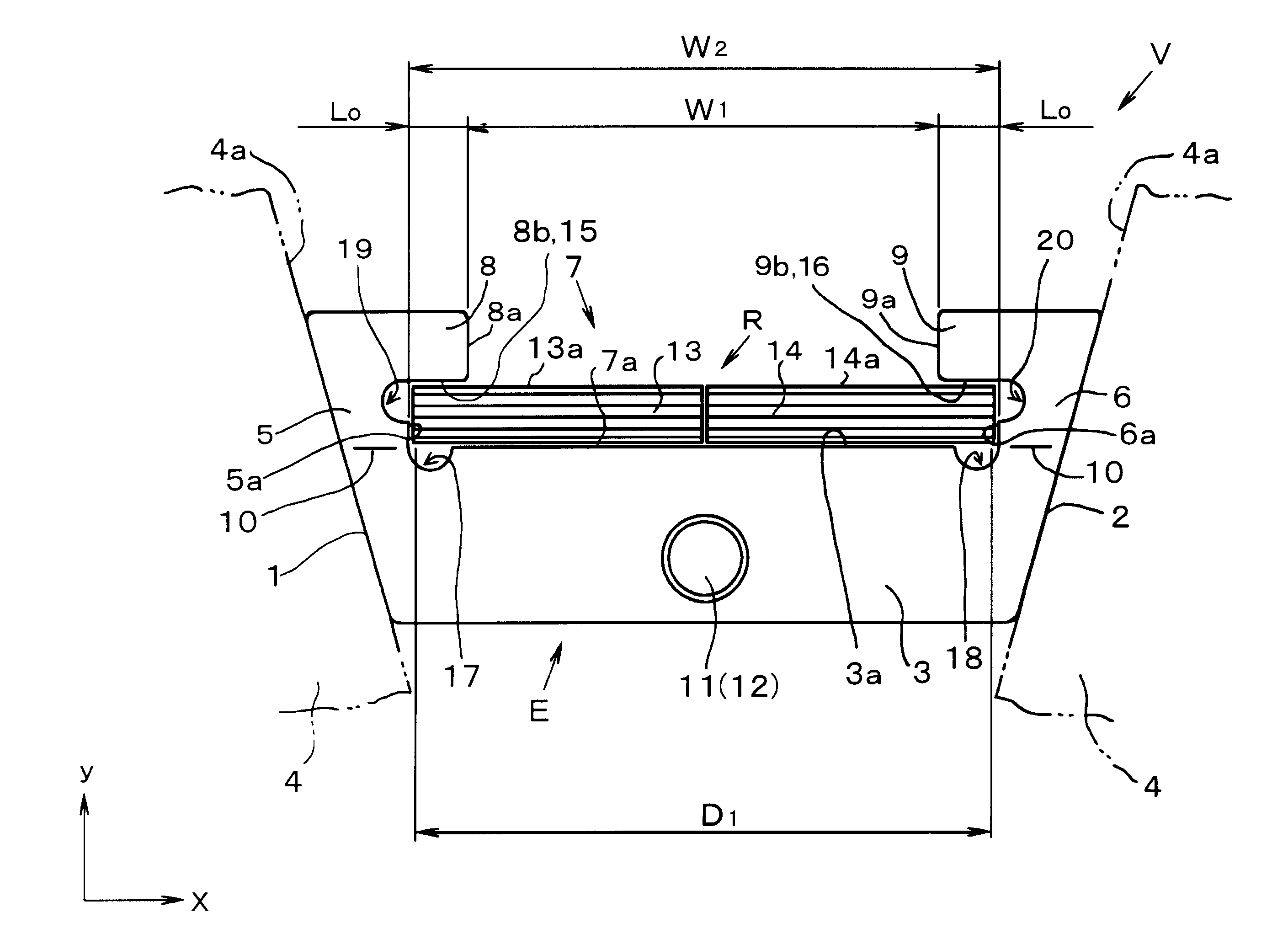
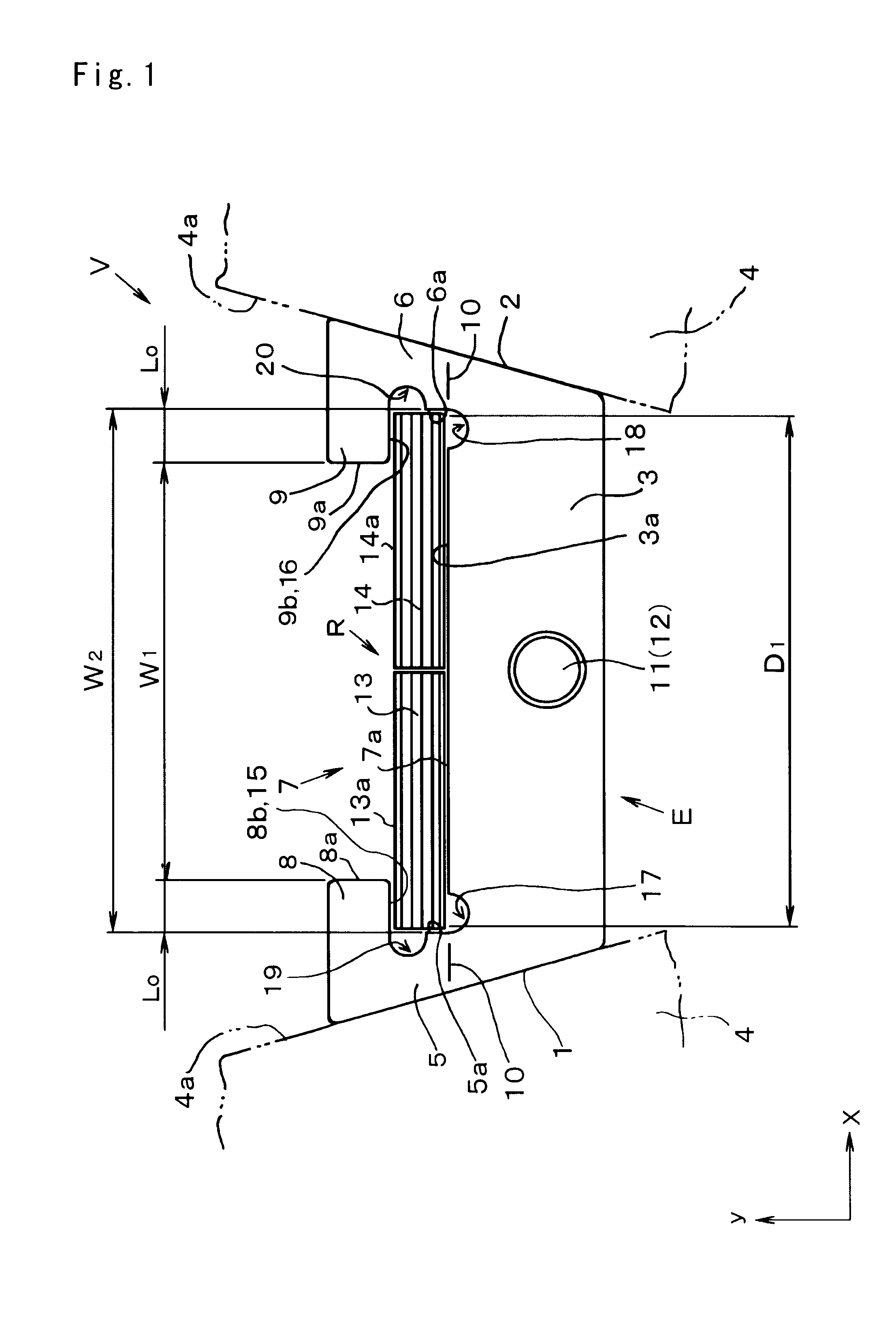
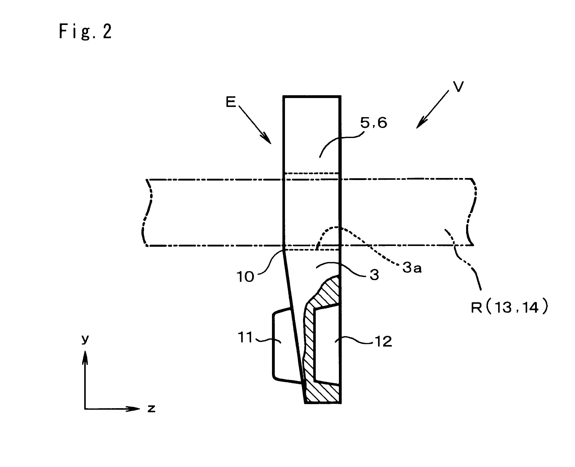
[0028]Next, this invention will be explained with reference to the accompanying drawings. First of all, a first example of the element for a driving belt and a driving belt using the element of the first example will be explained with reference to FIGS. 1 to 3. A driving belt V shown in FIGS. 1 and 2 is adapted to be applied to a drive pulley (i.e., an input shaft) and a driven pulley (i.e., an output shaft) of a belt-type continuously variable transmission to transmit a torque between those pulleys. The driving belt V shown therein comprises an annular ring R and a plurality of plate-like elements E.

[0029]The element E is a metal plate member comprising a base portion (or main body) 3. Both lateral faces 1 and 2 of the base portion 3, that is, both lateral ends (in the direction of x-axis in FIG. 1) of the base portion 3 are inclined. The inclined lateral faces 1 and 2 are frictionally contacted with a V-shaped groove 4a of a drive or driven pulley 4 of the belt type continuously v...

second example

[0060]Next, here will be explained a second example of the element for a driving belt and the driving belt using such element with reference to FIGS. 5 and 6. According to the second example of the present invention, a curved face protruding toward the inner circumferential side is formed on each holding face 15 and 16 of the element E of the first example. Therefore, a detailed explanation of the remaining structures in common with those of the first example will be omitted by allotting common reference numerals to FIGS. 5 and 6.

[0061]As shown in FIGS. 5 and 6, the element E of the second example comprises a curved face 21 formed on the inner face 8b of the latch portion 8, and a curved face 22 formed on the inner face 9b of the latch portion 9. Specifically, as shown in FIG. 6, a cross-sectional shape of each curved face 21 and 22 perpendicular to the thickness direction of the element E is an arcuate having a radius r2, and the curved face 21 and 22 protrude toward the inner circ...


PUM


Abstract

An element for a driving belt, which is easy for a ring to be fitted into a recess of the element, and which is capable of preventing deterioration of durability thereof. The element as a plate-like member includes latch portions formed on an opening end side of each inner side wall of the recess to hold a ring in its inner circumferential side. The element thus structured is juxtaposed in a circular manner to be fastened by the ring to form a driving belt. In the element, a holding face is formed on an inner circumferential face of the latch portion to be opposed to an outer circumferential face of the ring and to be contacted with the outer circumferential face of the ring to hold the ring, and a relief area is formed by depressing a portion of each of the inner side wall at an inner circumferential side of the holding face.

Description

TECHNICAL FIELD[0001]This invention relates to an element to be juxtaposed and fastened in a circular manner by an annular ring to form a driving belt, and to a driving belt using such elements.BACKGROUND ART[0002]In the prior art, a geared transmission adapted to change a speed change ratio stepwise, and a continuously variable transmission capable of varying a speed change ratio steplessly are available as a transmission mechanism for transmitting power between rotary members. For example, a belt-type continuously variable transmission and a toroidal-type continuously variable transmission are known as the continuously variable transmission. Specifically, the belt-type continuously variable transmission is adapted to vary a speed change ratio continuously using a pair of drive pulleys and a pair of driven pulleys, and a driving belt applied to those pulleys. The known endless driving belt used in such belt-type continuously variable transmission is prepared by juxtaposing a plural...

Claims


Application Information

Patent Timeline
Patent Type & Authority Applications(United States)
IPC IPC(8): F16G1/24
CPCF16G5/16
Inventor KOBAYASHI, DAISUKE
Owner TOYOTA JIDOSHA KK
Why Eureka
Try Eureka