Hot and cold water dispenser

a dispenser technology, applied in the field of hot and cold water dispensers, can solve the problems of deteriorating cooling efficiency, inability to meet the needs of customers, so as to improve cooling or heating efficiency, reduce energy consumption, and minimize the volume of cold water tanks

Inactive Publication Date: 2011-08-25
CHOI SANG PIL
View PDF13 Cites 10 Cited by
  • Summary
  • Abstract
  • Description
  • Claims
  • Application Information

AI Technical Summary

Benefits of technology

[0013]The hot and cold water dispenser according to the present invention can minimize energy consumption and immediately provide cold water or hot water by a user's demand by enhancing cooling or heating efficiency. Moreover, the hot and cold water dispenser can minimize the volume of the cold water tank or the hot water tank and enhance sealability, so that the user can easily install it on a sink or a small water purifier.

Problems solved by technology

However, the cold water tank of the prior art deteriorates the cooling efficiency because one side of the cooling pipe is in contact with the outer circumference of the cold water tank and the other side is exposed to the outside.
Of course, because a heat insulator is disposed on the outer face of the cooling pipe, it can prevent that the cooling efficiency is deteriorated greatly, but some loss is inevitable.
Additionally, because the cooling pipe is disposed on the outer circumference of the cold water tank, it may be directly exposed to the external shock during the manufacturing process or the installation process.

Method used


Image

  • Hot and cold water dispenser
  • Hot and cold water dispenser
  • Hot and cold water dispenser

Examples


Embodiment Construction

[0046]Reference will be now made in detail to the preferred embodiment of the present invention with reference to the attached drawings.

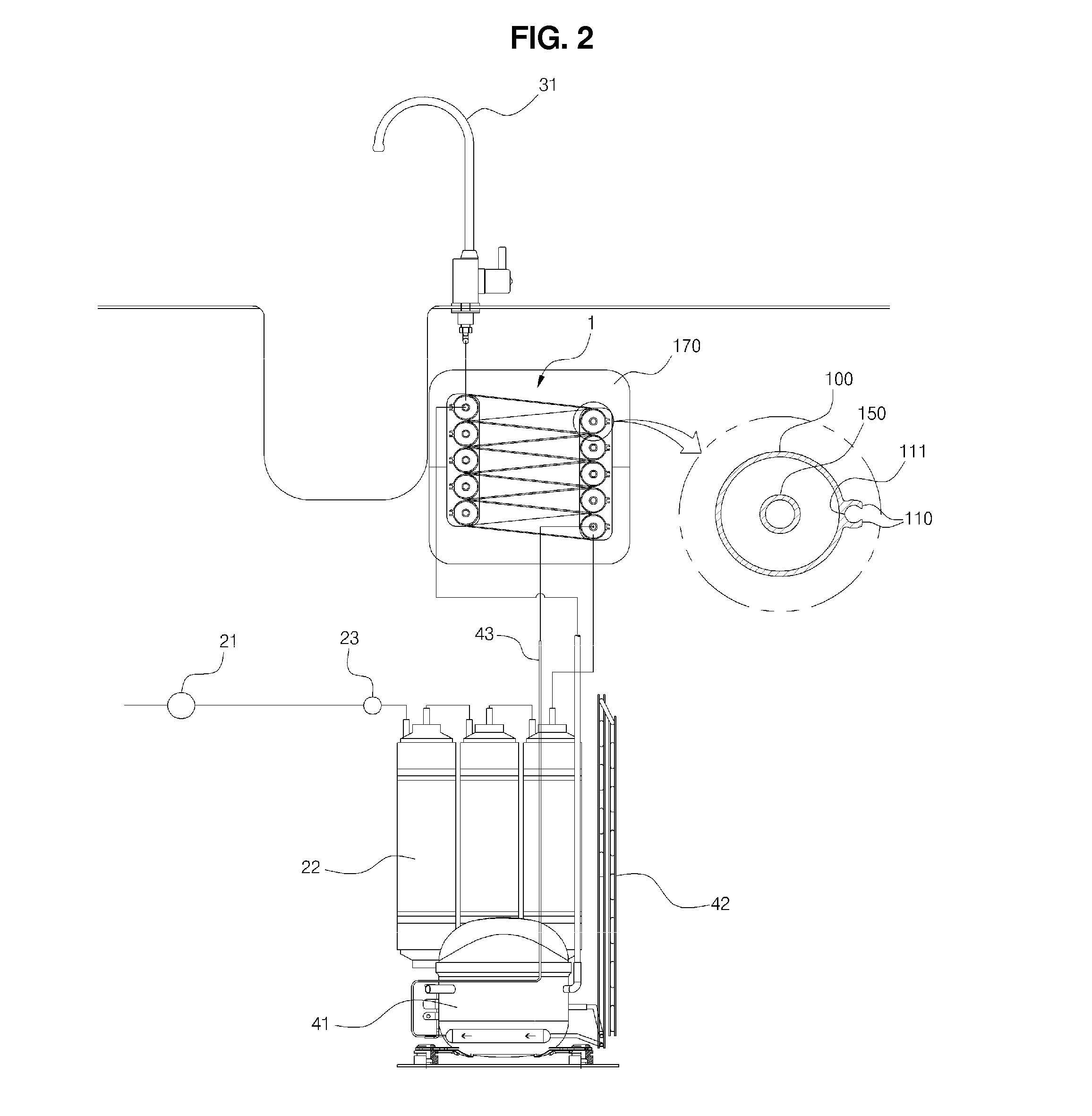
[0047]FIG. 1 is a view showing a structure of a cold water tank of a hot and cold water dispenser according to the present invention, and FIG. 2 is a schematic diagram of the hot and cold water dispenser having the cold water tank of FIG. 1.

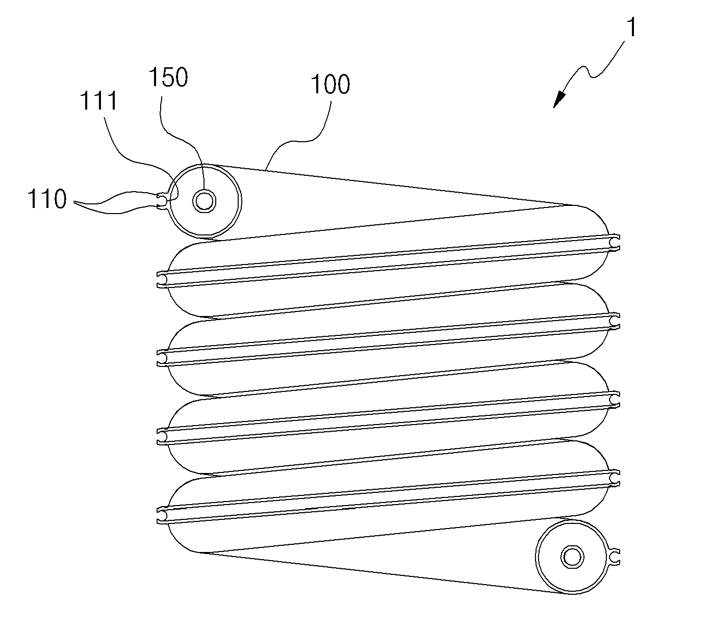
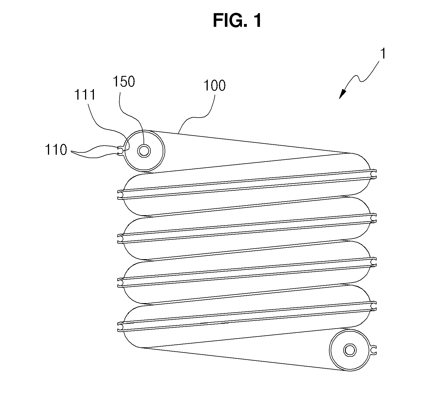
[0048]Referring to FIGS. 1 and 2, a hot and cold water pipe 1 of the hot and cold water dispenser according to the present invention includes a feed pipe 100 and a temperature control pipe 150.

[0049]The feed pipe 100 has a hollow part in which water flows. The feed pipe 100 or the hollow part may be circular or polygonal in cross section form, and preferably, is in a circular form.

[0050]The feed pipe 100 is in a coiled form that the feed pipe 100 is turned at least once, the coiled feed pipe 100 is combined with and lies upon another feed pipe 100, which is adjacent thereto, and hence, the feed pipes 100 have a l...


PUM


Abstract

Disclosed therein is a hot and cold water dispenser, which includes cooling means or heating means for cooling or heating water. The hot and cold water dispenser includes: a feed pipe having a flow path formed therein for allowing a flow of water; and a temperature control pipe disposed inside or outside of the feed pipe along a longitudinal direction of the feed pipe, the temperature control pipe having a space for receiving the cooling means or the heating means therein to cool or heat water flowing through the feed pipe by means of the cooling means or the heating means.

Description

CROSS REFERENCE TO RELATED APPLICATIONS[0001]This application claims the benefit and priority of Patent Application Nos. KR 10-2010-0015871 filed Feb. 22, 2010; KR 10-2010-0015872 filed Feb. 22, 2010; KR 10-2010-0015870 filed Feb. 22, 2010; KR 10-2010-0072224 filed Jul. 27, 2010; KR 10-2010-0072544 filed Jul. 27, 2010; KR 10-2010-0090215 filed Sep. 14, 2010; KR 10-2010-0127466 filed Dec. 14, 2010 and KR 10-2011-0008979 filed Jan. 28, 2011. The entire disclosures of the above applications are incorporated herein by reference.BACKGROUND OF THE INVENTION[0002]1. Field of the Invention[0003]The present invention relates to a hot and cold water dispenser, and more particularly, to a hot and cold water dispenser, which includes a feed pipe, a temperature control pipe formed integrally with the feed pipe to directly carry out heat exchange, and a cooling pipe disposed at the central portion of a cold water tank, thereby enhancing cooling efficiency or heating efficiency and effectively uti...

Claims


Application Information

Patent Timeline
Patent Type & Authority Applications(United States)
IPC IPC(8): F25D3/00B67D7/74
CPCF25D31/002F24H1/142F24D17/0026F24D19/1051F24D17/0073F24D17/0089F24D17/0031F24H15/20F24H15/248
Inventor CHOI, SANG PIL
Owner CHOI SANG PIL
Why Eureka
Try Eureka