Wire feed speed referenced variable frequency pulse welding system

a variable frequency pulse and wire feed technology, applied in the field of welding, can solve the problems of rapid changes in the feed speed of wires, difficult control of wire feed rates, and difficulty in controlling wire feed rates

Active Publication Date: 2011-08-25
ILLINOIS TOOL WORKS INC
View PDF7 Cites 82 Cited by
  • Summary
  • Abstract
  • Description
  • Claims
  • Application Information

AI Technical Summary

Problems solved by technology

While very effective in many applications, such pulsed regimes render control of wire feed rates difficult.
This may require rapid changes in wire feed speed, however, rendering control difficult.
These difficulties are exacerbated when certain types of wire are used, such as aluminum and its alloys.
Such coordination is difficult and often leads to less than optimal system performance.

Method used


Image

  • Wire feed speed referenced variable frequency pulse welding system
  • Wire feed speed referenced variable frequency pulse welding system
  • Wire feed speed referenced variable frequency pulse welding system

Examples


Embodiment Construction

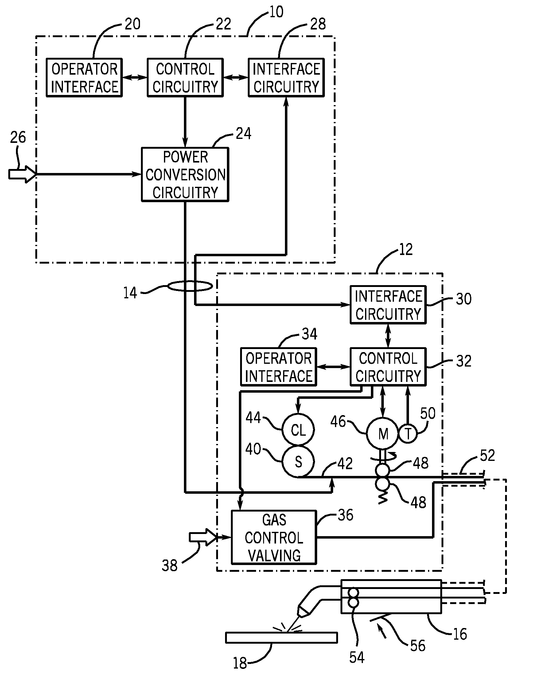
[0015]Turning now to the drawings, and referring first to FIG. 1, an exemplary welding system is illustrated as including a power supply 10 and a wire feeder 12 coupled to one another via conductors or conduits 14. In the illustrated embodiment the power supply 10 is separate from the wire feeder 12, such that the wire feeder may be positioned at some distance from the power supply near a welding location. However, it should be understood that the wire feeder, in some implementations, may be integral with the power supply. In such cases, the conduits 14 would be internal to the system. In embodiments in which the wire feeder is separate from the power supply, terminals are typically provided on the power supply and on the wire feeder to allow the conductors or conduits to be coupled to the systems so as to allow for power and gas to be provided to the wire feeder from the power supply, and to allow data to be exchanged between the two devices as described more fully below.

[0016]The ...


PUM

PropertyMeasurementUnit
welding poweraaaaaaaaaa
speedaaaaaaaaaa
feed speedaaaaaaaaaa

Abstract

A pulsed waveform welding operation is implemented by reference to a commanded wire feed speed set by an operator. The wire feed speed is set on a wire feeder, and a signal representative of the commanded wire feed speed is applied to a power supply. The power supply control circuitry references a look-up table in which pulsed waveform parameters are provided based upon wire feed speed. The parameters may include multiple parameters such as pulse frequency, peak current, background current, and current ramp rates. The control circuitry commands power conversion circuitry to generate the commanded waveform as a function of the commanded wire feed speed.

Description

BACKGROUND[0001]The invention relates generally to welders, and more particularly to a welder configured to perform a welding operation in which a pulsed waveform is applied to welding wire as the wire is advanced from a welding torch.[0002]A wide range of welding systems and welding control regimes have been implemented for various purposes. In continuous welding operations, metal inert gas (MIG) techniques allow for formation of a continuing weld bead by feeding welding wire shielded by inert gas from a welding torch. Electrical power is applied to the welding wire and a circuit is completed through the workpiece to sustain an arc that melts the wire and the workpiece to form the desired weld.[0003]Advanced forms of MIG welding are based upon generation of pulsed power in the welding power supply. That is, various pulsed regimes may be carried out in which current and / or voltage pulses are commanded by the power supply control circuitry to regulate the formation and deposition of ...

Claims


Application Information

Patent Timeline
Patent Type & Authority Applications(United States)
IPC IPC(8): B23K9/09B23K9/10B23K9/12
CPCB23K9/09B23K9/1336B23K9/173B23K9/0953B23K9/092B23K9/133
Inventor SCHARTNER, QUINN W.NELSON, ANDREW D.
Owner ILLINOIS TOOL WORKS INC
Why Eureka
Try Eureka