Circuit arrangement for operating a discharge lamp

a discharge lamp and circuit arrangement technology, which is applied in the direction of lighting devices, electrical equipment, light sources, etc., can solve the problems of limited circuit voltage ocv to the output load, circuit does not provide appropriate output characteristics, and the current provided by the resonant circuit to the lamp load is usually insufficient to sustain the ar

Inactive Publication Date: 2011-08-25
PANASONIC CORP
View PDF6 Cites 1 Cited by
  • Summary
  • Abstract
  • Description
  • Claims
  • Application Information

AI Technical Summary

Benefits of technology

[0026]According to another object of the present invention, an apparatus is disclosed for operating a gas discharge lamp. The apparatus includes an electronic ballast and a controller. The electronic ballast includes a first inductance-capacitance network that is formed of a first inductance and a first capacitance, a second inductance-capacitance network that is formed of a second inductance and a second capacitance, a first half bridge configuration that utilizes the first inductance-capacitance network in an igniter function, and a second half bridge configuration that is utilized with the first half bridge configuration as a full bridge configuration, in which the full bridge configuration utilizes the second inductance-capacitance network in a buck inverter function. The controller controls the first half bridge configuration to ignite an arc between electrodes of a gas discharge lamp using the igniter function. The controller also controls the electronic ballast to change from the first half bridge configuration to the full bridge configuration after the arc is ignited, so that the buck inverter function of the full bridge configuration sustains the arc between the electrodes of the gas discharge lamp. In addition, the controller engages a transient operation function to produce a swing voltage across the first inductance to effect re-ignition of the arc between the electrodes of the gas discharge lamp at least when the arc extinguishes. It is noted that the swing voltage is generated by the first half bridge configuration.

Problems solved by technology

However, once the lamp is ignited by the certain high peak voltage, the current provided from the resonant circuit to the lamp load is usually insufficient to sustain the arc inside the lamp arc tube, as only a glow current flows through the lamp.
However, a maximum voltage OCV supplied by the circuit (electronic ballast) to the output load is limited by the applied DC voltage to the circuit.
Unfortunately, the above-described conventional circuit does not provide appropriate output characteristics for the glow-to-arc transition mode.
The igniter function of the conventional circuit provides a high peak voltage, but not enough sustaining current, while the buck inverter function provides an adequate RMS current, but not enough high peak voltage.
Specifically, the conventional circuit lacks the optimization of lamp glow-to-arc transition required for some HID lamps.

Method used


Image

  • Circuit arrangement for operating a discharge lamp
  • Circuit arrangement for operating a discharge lamp
  • Circuit arrangement for operating a discharge lamp

Examples


Embodiment Construction

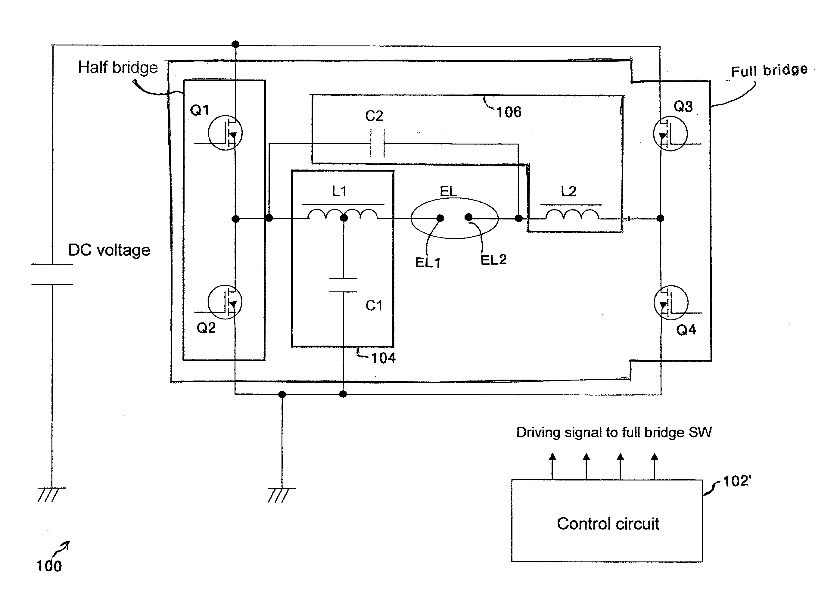
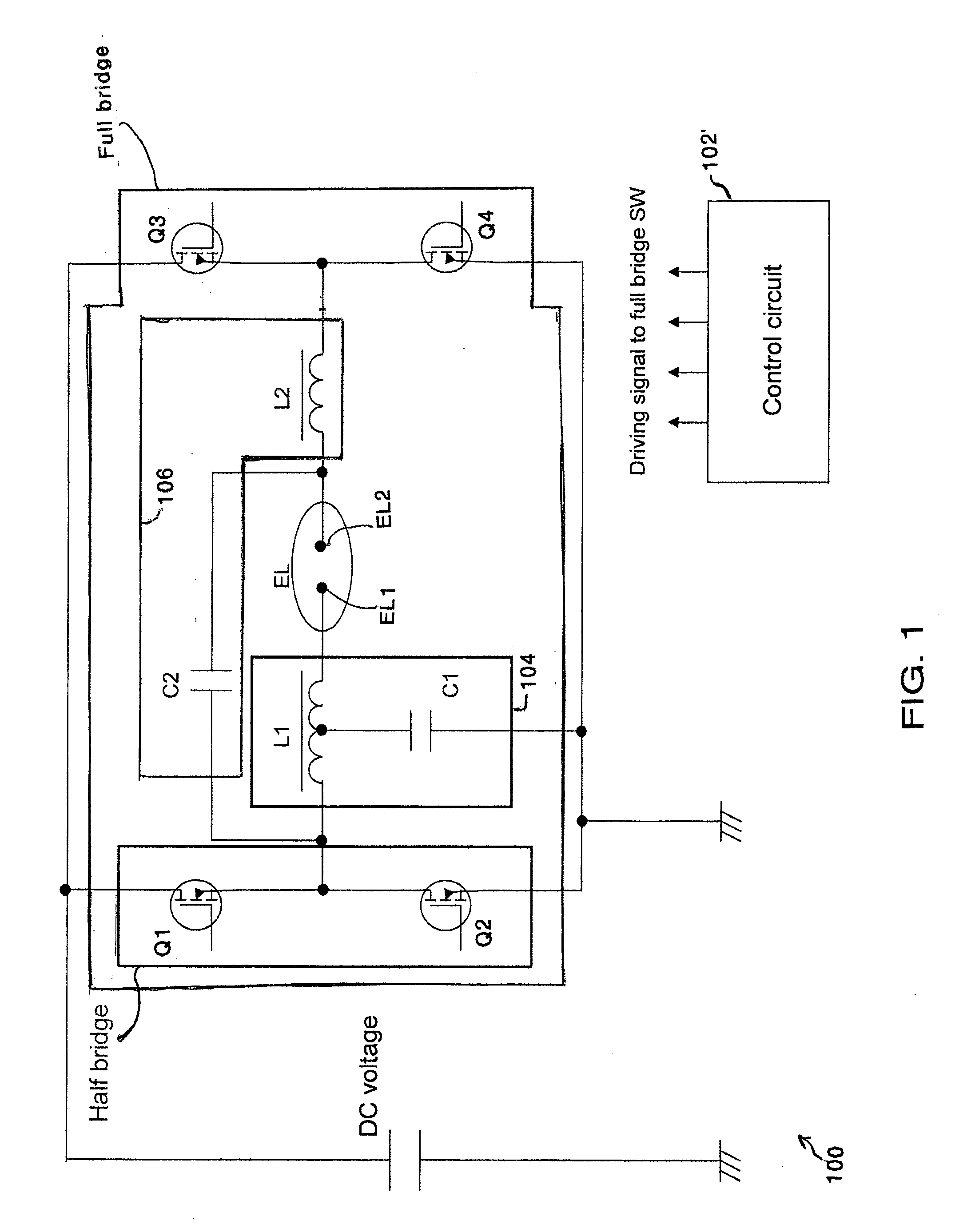
[0044]A simplified diagram of a conventional circuit arrangement 100 for driving a HID lamp EL is illustrated in FIG. 11. In the first function (i.e., igniter function), switches Q1 and Q2 are alternately turned ON and OFF by a controller 102 at a predetermined frequency, in order to generate a resonance in a first network 104 formed by a first inductance L1 and a first capacitance C1. The resonant action of the first inductance L1 and first capacitance C1 generates a high resonant voltage across the first inductance L1. The high resonant voltage is transferred to arc tube electrodes EL1 and EL2 of the HID lamp EL to ignite the HID lamp EL.

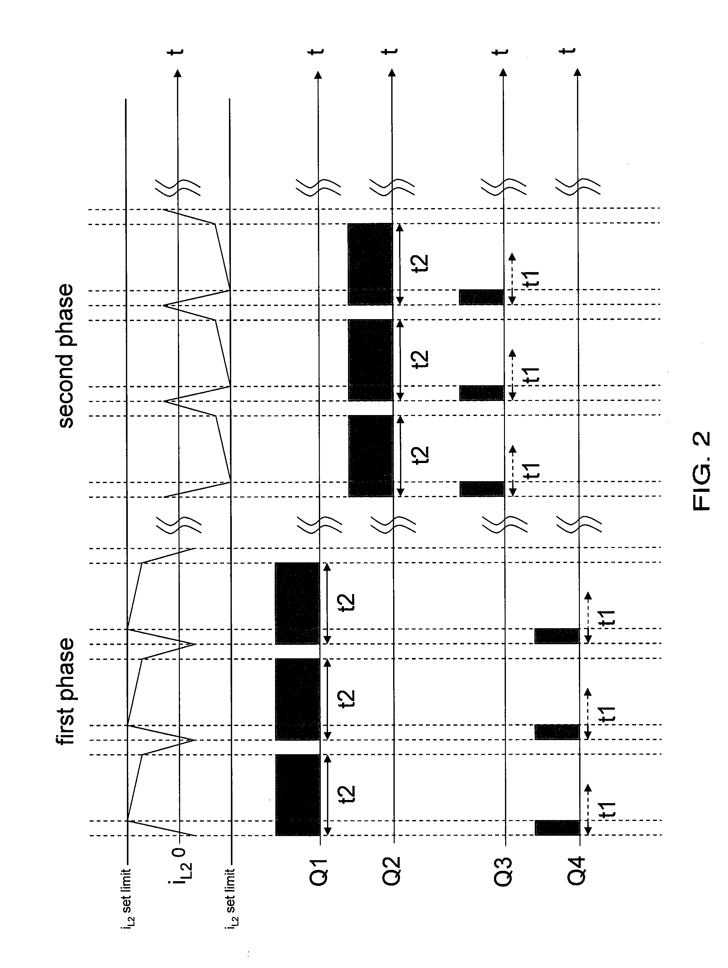
[0045]When the ignition of the HID lamp EL is detected by the controller 102, the circuit 100 switches to the second function (i.e., buck inverter function). The second function consists of two phases. The first phase is when switches Q1 and Q4 are actively controlled to regulate power across the HID lamp EL using a second network 106 formed by se...


PUM


Abstract

An apparatus for operating a gas discharge lamp. The apparatus includes an electronic ballast and a controller. The electronic ballast includes a half bridge configuration, a full bridge configuration, a first network, and a second network. The electronic ballast is controlled by a controller that causes the half bridge configuration to ignite an arc between electrodes of the gas discharge lamp in an igniter function that uses the first network, to switch the electronic ballast from the half bridge configuration to the full bridge configuration after the arc is ignited so that a buck inverter function using the second network sustains the arc between the electrodes of the gas discharge lamp, and to provide a transient operation function to the buck inverter function to produce a spike voltage that is used to re-ignite the arc between the electrodes of the gas discharge lamp when the arc extinguishes.

Description

BACKGROUND OF THE INVENTION[0001]1. Field of the Invention[0002]The present invention relates to High Intensity Discharge (HID) lamps, and more particularly, to an electronic ballast for use with an HID lamp.[0003]2. Background and Related Information[0004]Generally, there are two types of operation modes for HID lamps. In a first operation mode, generally referred to as a starting mode, a lamp arc tube (e.g., lamp) requires a certain high peak voltage, such as, for example, approximately 3 kV to approximately 5 kV, to ignite an arc between two electrodes in the lamp. In a second operation mode, generally referred to as a lighting mode, the lamp requires a certain RMS current that corresponds to an impedance between the two electrodes in the lamp in order to sustain (maintain) the arc, so that the lamp continues to emit light.[0005]In a conventional electronic ballast, a full bridge circuit may be employed, to which a DC voltage, typically less than 500V, is applied. This convention...

Claims


Application Information

Patent Timeline
Patent Type & Authority Applications(United States)
IPC IPC(8): H05B41/36
CPCH05B41/2883H05B45/375
Inventor FUKUDA, KENICHISUN, YIYOUNG
Owner PANASONIC CORP
Why Eureka
Try Eureka