RFID tag

a technology of rfid tags and tags, applied in the field of rfid tags, can solve the problems of inability to communicate, failure to operate, and deterioration of characteristics, so as to prevent interference, avoid the effect of deterioration of emission and receiving characteristics due to the effects of the human body and increase the gain

Inactive Publication Date: 2008-01-29
FUJITSU LTD
View PDF5 Cites 26 Cited by
  • Summary
  • Abstract
  • Description
  • Claims
  • Application Information

AI Technical Summary

Benefits of technology

[0016]The present invention was produced in light of the aforementioned problems and has the objective of offering an RFID tag in which, even when overlapped with a card-type 13 MHz band RFID tag, the effects of the 13 MHz band RFID card on the loop antenna are reduced, and good radiation and receiving characteristics can be obtained even when used in proximity with the human body.
[0021]In the present invention, due to the use of embodiments described above, even when a 13 MHz band RFID tag is superposed, sufficient current is generated on the coiled loop antenna to allow communication to be performed satisfactorily by the 13 MHz band RFID tag. This is done by preventing interference with the magnetic flux passing through the interior of the coiled loop antenna of the 13 MHz band RFID tag. Moreover, deterioration of emission and receiving characteristics due to the effects of the human body can be avoided, and gain can be increased at the same time as bandwidth is broadened.

Problems solved by technology

As a result, current is not supplied to the chip on the card-type 13 MHz band RFID tag, which fails to operate, and communication cannot be achieved.
As a separate problem from that described above, when a conventional UHF band RFID tag (e.g., a tag having a folded dipole antenna) is used in proximity to the human body, there has been the problem that the characteristics have deteriorated.
Moreover, while conventional tags having a ground plane may not suffer deterioration of characteristics in proximity to the human body, since the antenna has both a front and back side, characteristics have been known to deteriorate when the antenna element is turned toward the human body.

Method used


Image

  • RFID tag
  • RFID tag
  • RFID tag

Examples


Embodiment Construction

[0034]An embodiment of the present invention is next explained, with reference to the drawings.

[0035]FIG. 3 shows the configurations of a planar loop antenna according to the present invention. In FIG. 3, a metal part 11 the surface of which is partially cut-out is wrapped on a dielectric substrate 10, and the power supply position and mounting position of an IC chip 12 are shown in the vicinity of the cut-out portion.

[0036]FIG. 4 shows an example of the layout of a planar loop antenna in an RFID tag of the present invention.

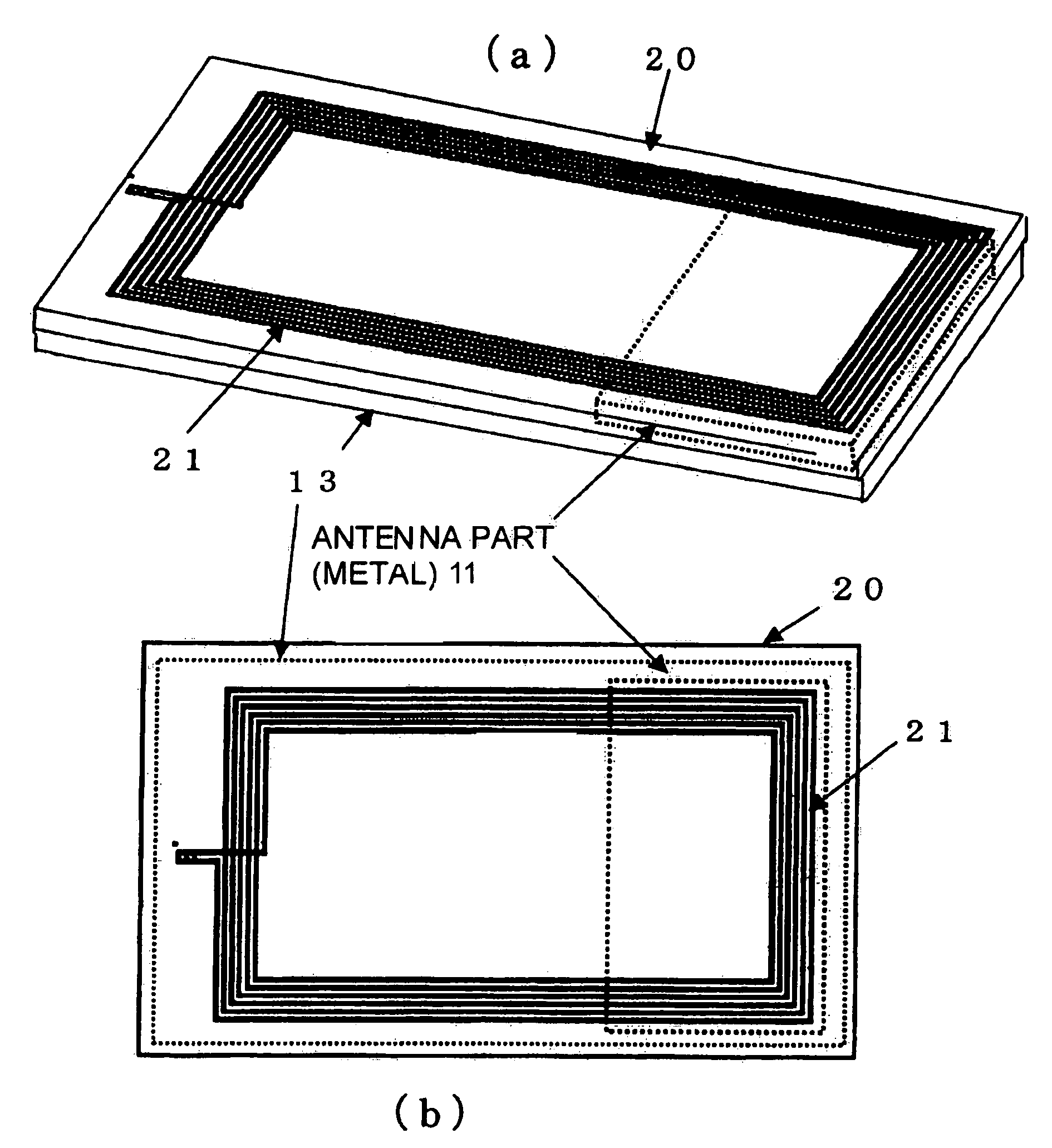
[0037]In FIG. 4, the planar loop antenna of FIG. 3 is placed inside the RFID tag 13 near the end thereof. FIG. 5 shows an example of the arrangement whereby a 13 MHz band RFID tag 20 is superposed on the RFID tag 13 of the present invention, such as UHF or 2.45 GHz tag FIG. 5(a) is a block diagram showing a lateral view and FIG. 5(b) is a block diagram showing a view from directly above.

[0038]FIGS. 5(a) and (b) assume that a 13 MHz band RFID tag 20 and the RFID ...


PUM


Abstract

An RFID tag which has improved radiation / reception characteristics when used in proximity to the human body, and has an antenna which, when stacked with a 13 MHz band RFID tag, does not have an effect on the loop antenna of that tag. An RFID tag assembly comprises a first RFID tag having a coiled loop antenna and a second RFID tag superposed on the first RFID tag, the second RFID tag comprising an antenna formed by a metal member which covers at least a portion of a surface of a dielectric substrate, an electronic part mounted on the metal member, and a member which is provided with the overlapped coiled loop antenna of the first RFID tag housed in the end thereof so as to cover a portion of the antenna formed by the metal member.

Description

CROSS REFERENCE TO RELATED APPLICATION[0001]This application is related to and claims priority to Japanese Application No. 2004-313061 filed Oct. 27, 2004 in the Japanese Patent Office, the contents of which are incorporated by reference herein.BACKGROUND OF THE INVENTION[0002]1. Field of the Invention[0003]The present invention relates to UHF-band RFID tags, and concerns an RFID tag in which, even when a card-type 13 MHz band RFID tag is included with it, the effects on the loop antenna of the 13 MHz band RFID card are reduced, and good radiation and receiving characteristics can be obtained even when used in proximity to the human body.[0004]2. Description of the Related Art[0005]The RFID tag is explained using a conventional folded dipole antenna.[0006]FIG. 1 shows the upper face of a thin RFID tag 500. A chip 510 placed on an aperture 550 is connected to contacts 525 on a flexible substrate 520, and the substrate 520 is has at least two folded dipole antennas 530 and 531 contain...

Claims


Application Information

Patent Timeline
Patent Type & Authority Patents(United States)
IPC IPC(8): G08B13/14
CPCG06K19/07749G06K19/07779G06K19/07786G06K19/07796H01Q1/2225H01Q7/00G06K19/077
Inventor YAMAGAJO, TAKASHIMANIWA, TORUKAI, MANABUHAYASHI, HIROYUKI
Owner FUJITSU LTD
Why Eureka
Try Eureka