Rechargeable battery charging method, rechargeable battery charge controlling device and battery pack

a rechargeable battery and charging method technology, applied in secondary cell servicing/maintenance, electrochemical generators, safety/protection circuits, etc., can solve the problems of battery voltage exceeding the protection voltage, battery voltage of some batteries may exceed the available maximum voltage of the battery, and the target value of the charger is reduced, so as to maximize the characteristics of rechargeable batteries, reduce the target value of the charger

Active Publication Date: 2011-08-25
SANYO ELECTRIC CO LTD
View PDF5 Cites 42 Cited by
  • Summary
  • Abstract
  • Description
  • Claims
  • Application Information

AI Technical Summary

Benefits of technology

[0037]Accordingly, in the case where a plurality of rechargeable batteries are connected to each other in series, the target value of the charging current is reduced with reference to a rechargeable battery with the highest battery voltage. Therefore, even if the battery voltages of the serially-connected rechargeable batteries are unbalanced, it is possible to properly re

Problems solved by technology

However, in the case where the upper limit of the charging voltage is set higher than the protection voltage, a problem arises that, when a battery starts being charged at a relatively large setting current value, its battery voltage may exceed the available maximum voltage of the battery.
This problem tends to arise, for example, when the battery is quickly switched from

Method used


Image

  • Rechargeable battery charging method, rechargeable battery charge controlling device and battery pack
  • Rechargeable battery charging method, rechargeable battery charge controlling device and battery pack
  • Rechargeable battery charging method, rechargeable battery charge controlling device and battery pack

Examples


first embodiment

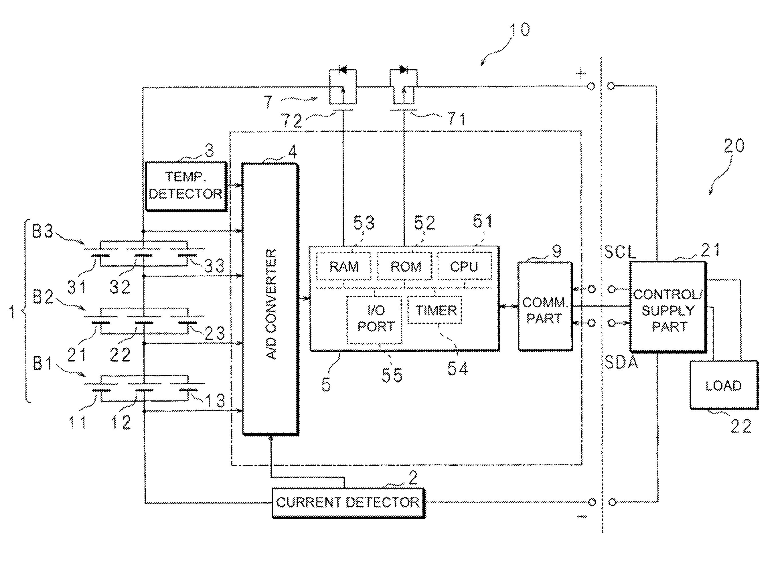
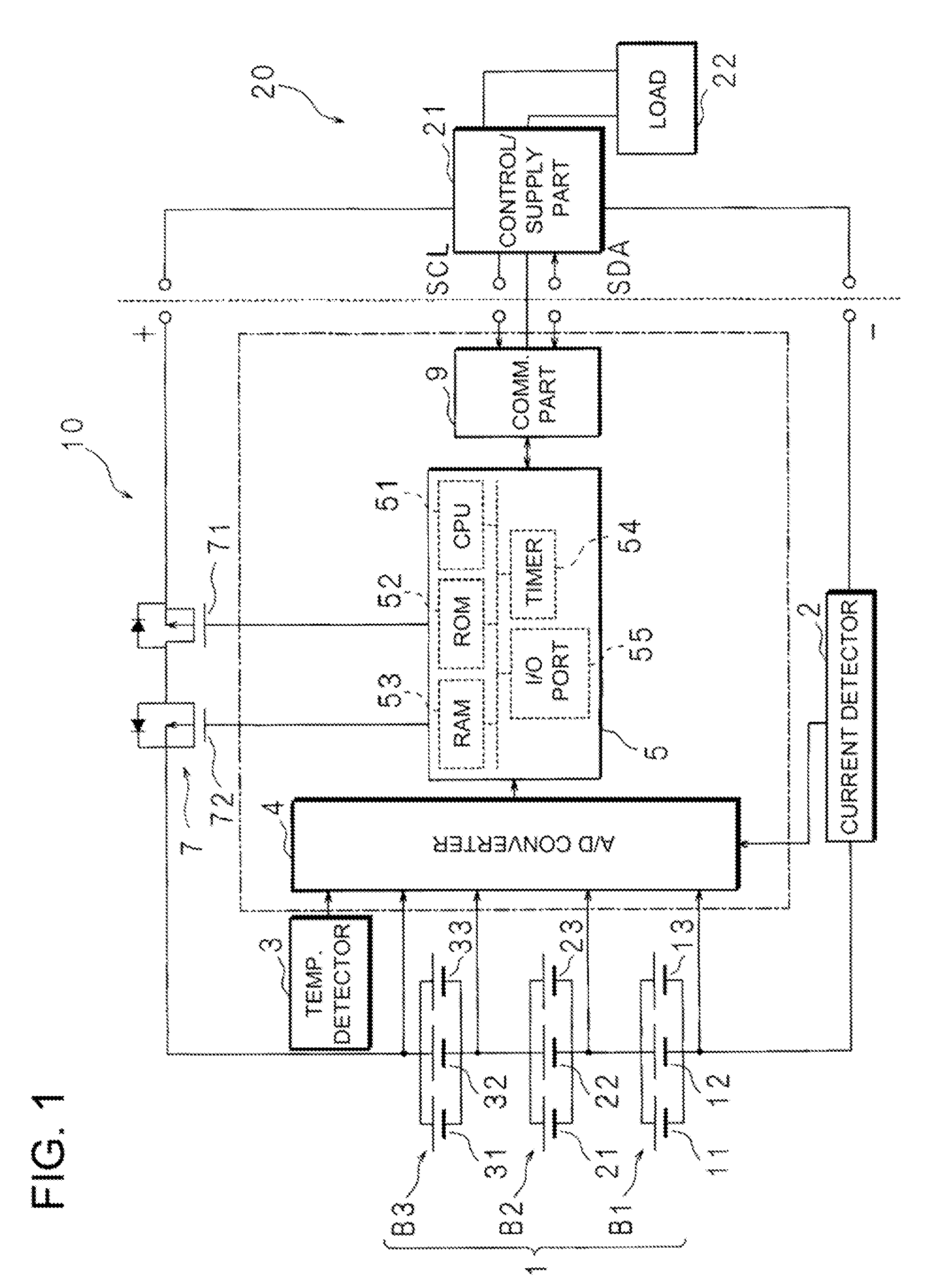
[0052]FIG. 1 is a block diagram showing the exemplary construction of a battery pack according to a first embodiment of the present invention. The battery pack includes a battery pack 10. The battery pack 10 is detachably attached to a load device 20 such as personal computer (PC) and personal digital assistant. The battery pack 10 includes a battery 1. The battery 1 includes battery blocks B1, B2 and B3 that are serially connected to each other in this order. Each of the battery blocks B1, B2 and B3 includes three battery cells of lithium-ion rechargeable batteries 11, 12 and 13, 21, 22 and 23, or 31, 32 and 33 that are connected to each other in parallel to each other. The positive terminal of the battery block B3 and the negative terminal of the battery block 61 serve as the positive terminal and the negative terminal of the battery 1, respectively.

[0053]The voltages of the battery block 61, B2 and 83 independently are provided to an analog input terminal of an A / D conversion por...

second embodiment

[0118]In the first embodiment, a parallel detection manner has been described where it is detected that the voltage of the battery block Bh exceeds the protection voltage and the setting voltage value. On the other hand, in the second embodiment, it detected that the voltage of the battery block Bh exceeds the protection voltage (or the setting voltage value) if the voltage of the battery block Bh exceeds the protection voltage until a predetermined period of time has elapsed after the voltage of the battery block Bh exceeds the setting voltage value (or, if the voltage of the battery block Bh does not exceeds the protection voltage until a predetermined period of time has elapsed).

[0119]FIG. 8 is a flowchart showing the procedure of the CPU 51 that sets a predetermined flag depending on the voltage of battery block Bh of the battery pack 10 according to the second embodiment of the present invention. The following procedure is performed periodically at a period of 250 ms in chargin...


PUM


Abstract

If a protection voltage (or setting voltage value) is continuously exceeded for two times (three times) by all of the voltage values of a battery block that are read periodically at a period of 250 ms, it is determined that the voltage of the battery block exceeds the protection voltage value of 4.32 V (or setting voltage value of 4.30 V) so that a target value of charging current is reduced to 0.1 C (or reduced to a value smaller than the currently-set target value) at the first determination. Every when it is detected that the voltage value exceeds the setting voltage value, the target value is reduced at a predetermined reduction rate. As a result, charging current is exponentially reduced whereby keeping the charging operation. At the second determination where the voltage of the battery block exceeds the protection voltage, a circuit breaker cuts off the charging current.

Description

BACKGROUND OF THE INVENTION[0001]1. Field of the Invention[0002]The present invention relates to a rechargeable battery charging method and a rechargeable battery charge controlling device that charge a rechargeable battery based on a target value of charging current, and a battery pack including this rechargeable battery charge controlling device.[0003]2. Description of the Related Art[0004]When charged, rechargeable batteries (hereinafter simply referred to as batteries) such as lithium ion batteries are typically charged at setting current and voltage values that fall within ranges not higher than the available maximum current and voltage (protection voltage for preventing the batteries from being overcharged) that are specified depending on the types of the batteries. Various charge controlling methods for this type of battery have been proposed in the past. In a most typical method, a battery is charged at charging voltage within a predetermined upper limit constantly at a sett...

Claims


Application Information

Patent Timeline
IPC IPC(8): H02J7/04
CPCH02J7/0029H02J7/041H01M10/44H01M10/0525H02J7/045H02J7/0071H02J7/007182H02J7/0013Y02E60/10H02J7/04H02J7/00302
Inventor KAINO, TOMOMI
Owner SANYO ELECTRIC CO LTD
Why Eureka
Try Eureka