Apparatus, device and computer implemented method for controlling power plant system

a technology of power plant and computer, applied in the direction of process and machine control, greenhouse gas reduction, instruments, etc., can solve the problem of unsurpassed performance and stable power

Active Publication Date: 2019-09-05
WARTSILA NORTH AMERICA INC
View PDF0 Cites 6 Cited by
  • Summary
  • Abstract
  • Description
  • Claims
  • Application Information

AI Technical Summary

Benefits of technology

[0047]if the forecasted energy flow information indicates negative forecasted energy flow and the energy storage has not enough available stored energy capacity to supply the forecasted energy and the spinning reserve, then decreasing the target value for the AC power.

Problems solved by technology

Delivery of stable power with unsurpassed performance and profitability with system modularity and intelligent control and data management increase the challenges even further.

Method used


Image

  • Apparatus, device and computer implemented method for controlling power plant system
  • Apparatus, device and computer implemented method for controlling power plant system
  • Apparatus, device and computer implemented method for controlling power plant system

Examples


Embodiment Construction

[0108]In the following description, like numbers denote like elements.

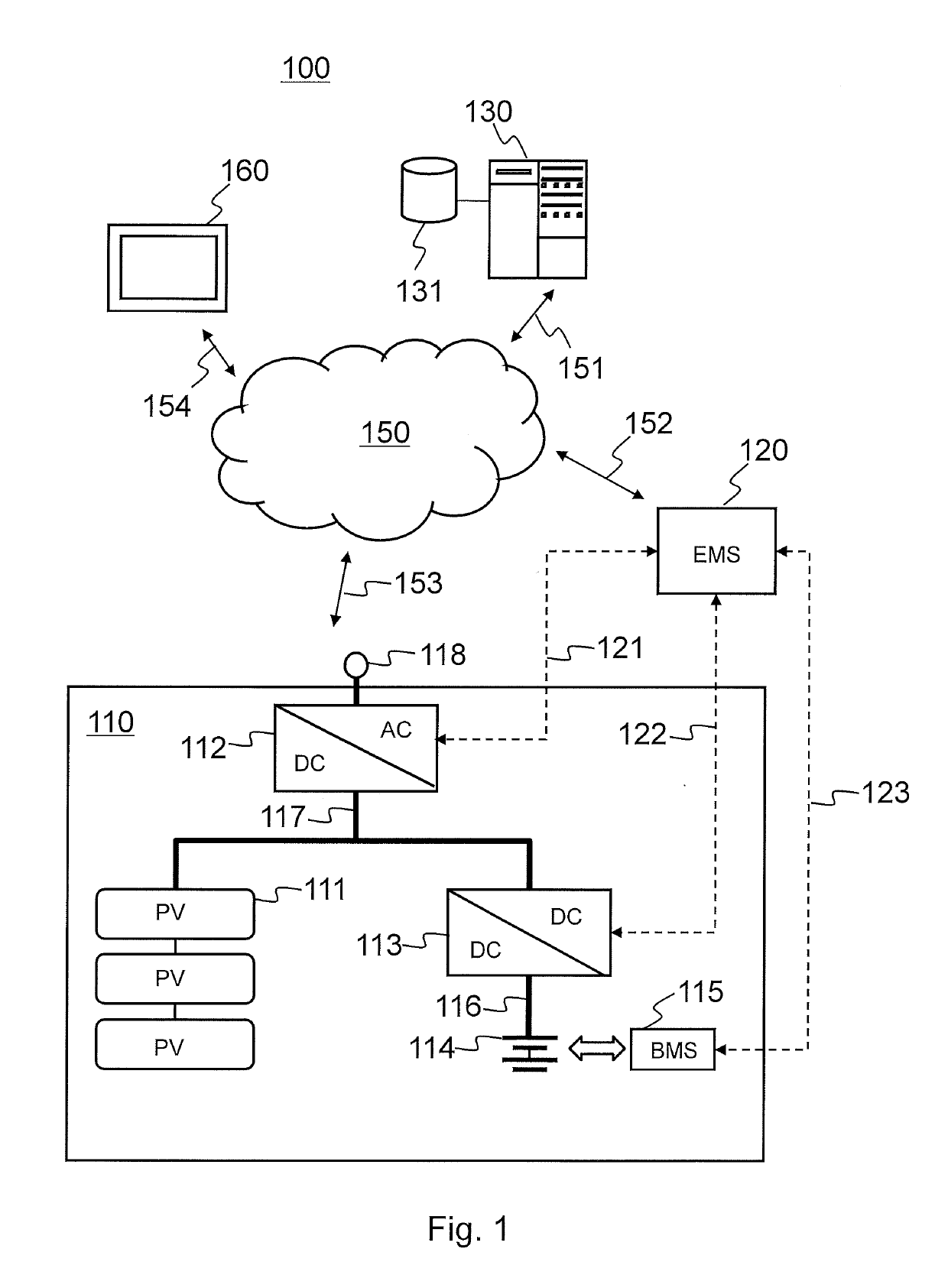
[0109]FIG. 1 shows a schematic picture of a system 100 according to an example embodiment.

[0110]The power plant system 100 may comprise a power plant subsystem 110 and a controller apparatus (EMS) 120 as separate entities, where the controller apparatus 120 may be remote to the subsystem 110 or the subsystem 110 and the control apparatus 120 may be arranged on the same sub-system 110, 120.

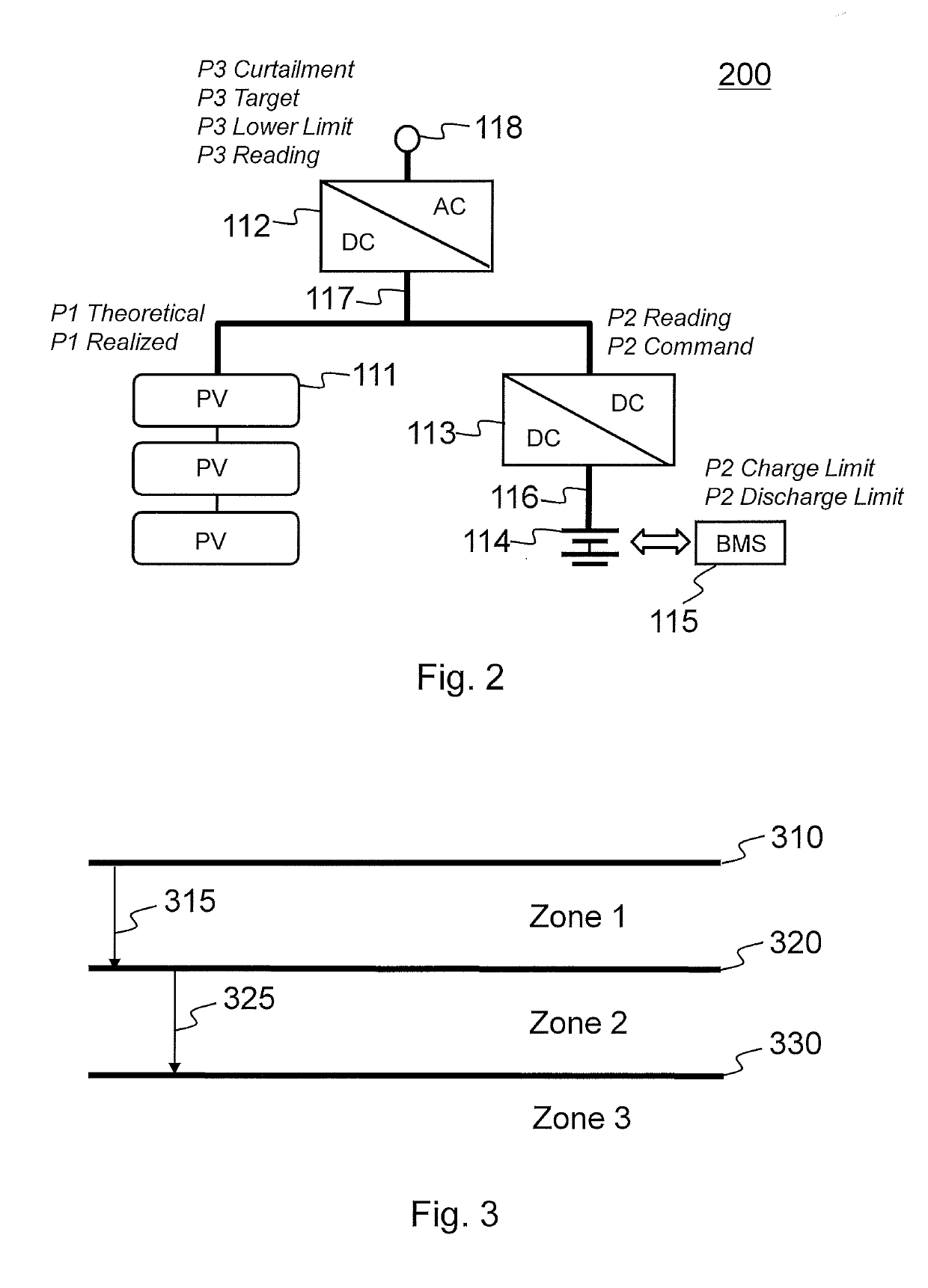
[0111]A power plant system 100 comprises a photovoltaic power source 111 to provide photovoltaic DC power to a photovoltaic DC bus 117, an inverter 112 comprising a direct current (DC) power input operationally connected to the photovoltaic DC bus 117 to receive photovoltaic DC power, and an alternating current (AC) power output for supplying AC power to an AC system 118.

[0112]The power plant system 100 further comprises a DC-to-DC converter 113 comprising a first direct current (DC) port to be operationally connected to the phot...


PUM


Abstract

A computer implemented method for controlling a power plant system comprising a photovoltaic power source, an inverter, a DC-to-DC converter, an energy storage and an energy storage manager, the method comprising: receiving target value for AC power to be supplied by the inverter; receiving weather forecast information, energy storage status information and photovoltaic power source parameters; generating forecasted energy flow information for the photovoltaic power source based on the weather information and the photovoltaic power source parameters; comparing the forecasted energy flow information and the energy storage status information; and adjusting the target value for the AC power based on the comparison.

Description

TECHNICAL FIELD[0001]The present application generally relates to an apparatus, a device, a method and software code for controlling a power plant system and / or an energy storage system. The present application further relates to a method, an apparatus and software code for integrating an energy storage system to a power plant system that includes a renewable energy source.BRIEF DESCRIPTION OF RELATED DEVELOPMENTS[0002]This section illustrates useful background information without admission of any technique described herein representative of the state of the art.[0003]Modern energy storage systems are fundamentally changing the way the customers approach energy storage. Desired systems should accelerate deployment, reduce costs and risk associated with installing energy storage. A distributed energy storage platform may be bundled with the advanced software controls to optimize savings, aggregate distributed energy resources, fortify grid resiliency and reliability and integrate ren...

Claims


Application Information

Patent Timeline
Patent Type & Authority Applications(United States)
IPC IPC(8): H02J3/38H02M3/145H01L31/042H02J3/32H02M1/00
CPCH02J3/385H02M3/145H02M2001/0067H02J3/32H02M1/00H01L31/042H02J3/003H02J2300/24H02J3/381Y02E70/30Y02A30/00Y02E10/56Y04S10/50H02J3/466H02J3/004H02J3/38H02M1/0067
Inventor ZHANG, SEN
Owner WARTSILA NORTH AMERICA INC
Why Eureka
Try Eureka