Fuel cell system and control method for fuel cell

a fuel cell and control method technology, applied in the direction of fuel cells, electrochemical generators, electrical equipment, etc., can solve the problems of insufficient power generation efficiency of fuel cells, inability to generate electric power at sufficient efficiency, and inability to always increase the electric power generated to an unlimited exten

Active Publication Date: 2005-06-02
HONDA MOTOR CO LTD
View PDF1 Cites 9 Cited by
  • Summary
  • Abstract
  • Description
  • Claims
  • Application Information

AI Technical Summary

Benefits of technology

[0026] Preferably, in the control method as mentioned above, the correcting step decreases the target value when a detected intake air temperature increases.

Problems solved by technology

Moreover, since the electric power consumption of the compressor increases accompanying an increase in the electric power generated, it is not always efficient to increase the electric power generated to an unlimited extent.
However, the power generation efficiency of the fuel cell is insufficient if only the target generated current is considered, and it varies in accordance with environmental factors such as ambient temperature and pressure and the like.
Therefore, there is the problem that in control with the aforementioned conventional technology, generation of electric power at sufficient efficiency is not possible in some cases.

Method used


Image

  • Fuel cell system and control method for fuel cell
  • Fuel cell system and control method for fuel cell
  • Fuel cell system and control method for fuel cell

Examples


Embodiment Construction

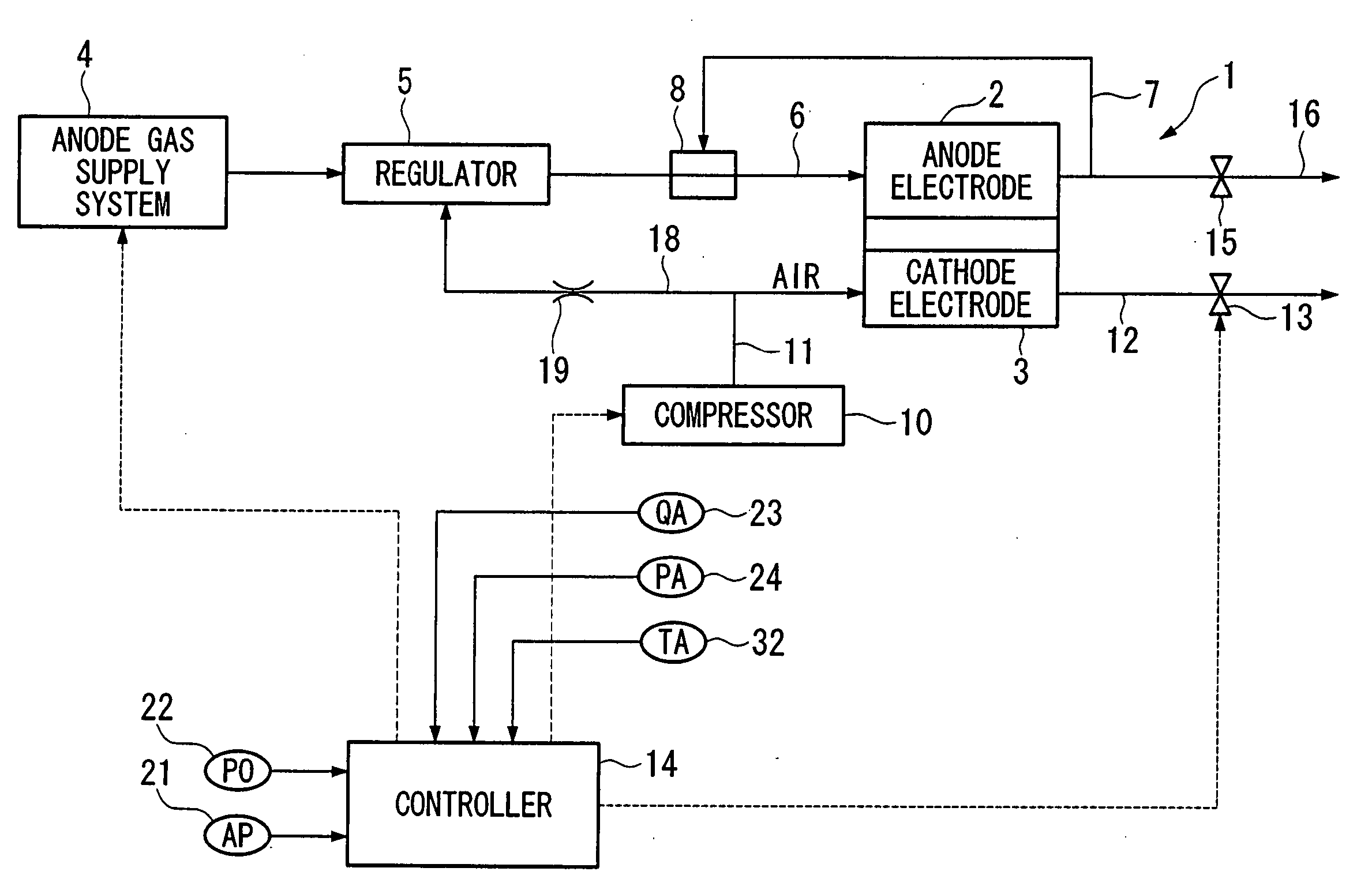
[0037] Hereunder is a description of a fuel cell system according to the present invention, with reference to the drawings. FIG. 1 is a block diagram of the fuel cell system in a first embodiment of the present invention.

[0038] A fuel cell (FC) 1 comprises cells of solid polymer electrolyte membrane formed from a solid polymer ion exchange membrane or the like, sandwiched between an anode electrode 2 and a cathode electrode 3, with a plurality of layers of cells each sandwiched between separators (FIG. 1 is a simplified diagram and therefore only a single cell is shown). When hydrogen gas is supplied to the anode electrode 2 as fuel gas, and air including oxygen is supplied to the cathode electrode 3 as reaction gas, hydrogen ions generated by the catalytic reaction at the anode electrode 2 pass through the solid polymer electrolyte membrane and migrate to the cathode electrode 3, giving rise to an electrochemical reaction with oxygen at the cathode electrode 3, and generating elec...


PUM

PropertyMeasurementUnit
electric poweraaaaaaaaaa
cathode pressureaaaaaaaaaa
atmospheric pressureaaaaaaaaaa

Abstract

A fuel cell system includes: a fuel cell which generates electricity by supplying hydrogen to an anode electrode, and a reaction gas to a cathode electrode, an anode gas supply device which supplies hydrogen to the anode electrode, and a cathode gas supply device which drives a compressor using electric power generated by the fuel cell, and supplies pressurized reaction gas to the cathode electrode. The fuel cell system further includes a target pressure setting device which sets a target value for cathode pressure of the fuel cell, a correction device which corrects the target value in accordance with atmospheric pressure, and a control device which controls the cathode pressure of the fuel cell to the corrected target value. Efficient electric power generation can be performed in accordance with the ambient environment.

Description

BACKGROUND OF THE INVENTION [0001] 1. Field of the Invention [0002] Priority is claimed on Japanese Patent Application No. 2003-398917, filed Nov. 28, 2003, the contents of which are incorporated herein by reference. [0003] The present invention relates to a fuel cell system having an anode gas supply device which supplies hydrogen to an anode electrode, and a cathode gas supply device which drives a compressor using electric power generated by the fuel cell, and supplies pressurized reaction gas to the cathode electrode. The present invention also relates to a control method for a fuel cell. [0004] 2. Description of Related Art [0005] Recently, the development of fuel cell vehicles using electricity generated by a fuel cell is proceeding. [0006] As this type of fuel cell vehicle, there is one where an anode gas supply device which supplies hydrogen to an anode electrode, and a compressor which supplies reaction gas to a cathode electrode are mounted within a vehicle, and hydrogen i...

Claims


Application Information

Patent Timeline
Patent Type & Authority Applications(United States)
IPC IPC(8): H01M8/00H01M8/04
CPCH01M8/04097H01M8/04111H01M8/0432Y02E60/50H01M8/0438H01M8/04395H01M8/04753H01M8/04335
Inventor OJIMA, KUNIAKIMURAKAMI, YOSHIKAZUYOSHIKAWA, SHINJIUEHARA, JUNJIUEDA, KENICHIRO
Owner HONDA MOTOR CO LTD
Why Eureka
Try Eureka