Wing Structure for WIG Vehicle

a technology for wigs and wing structures, applied in the direction of valve construction, machine/engine, air-flow influencers, etc., can solve the problems of undeveloped substitutes for vertical tail wings, problems such as affecting the performance of wig craft, and increasing air resistance and therefore fuel consumption, so as to reduce the weight of wig craft, reduce the weight of wigs, and suppress vortices and induced drag

Inactive Publication Date: 2011-08-25
WING SHIP TECH
View PDF12 Cites 5 Cited by
  • Summary
  • Abstract
  • Description
  • Claims
  • Application Information

AI Technical Summary

Benefits of technology

The wing structure for a WIG craft according to the invention is capable of suppressing vortices and induced drag generated on both ends of the left and right main wings while increasing lift and thrust, and compensating for asymmetry in thrust, which is between the left and right lateral ends when the WIG craft moves, under the control of the driving unit of the body of the WIG craft.
Further, the vertical tail wing is removed from the rear portion of the body of the WIG craft to advantageously reduce the weight of the WIG craft, and the rudder is mounted on the rear surface of the left and right downward wings to advantageously ensure stability with respect to yawing through turning to the left or right from the body of the WIG craft.

Problems solved by technology

The vertical tail wing, mounted on a rear portion of the body of the WIG craft, in general is provided with a rudder, so that when the WIG craft operates, air resistance and therefore fuel consumption problematically increase.
However, a substitute for the vertical tail wing has not yet been developed.

Method used


Image

  • Wing Structure for WIG Vehicle
  • Wing Structure for WIG Vehicle
  • Wing Structure for WIG Vehicle

Examples


second embodiment

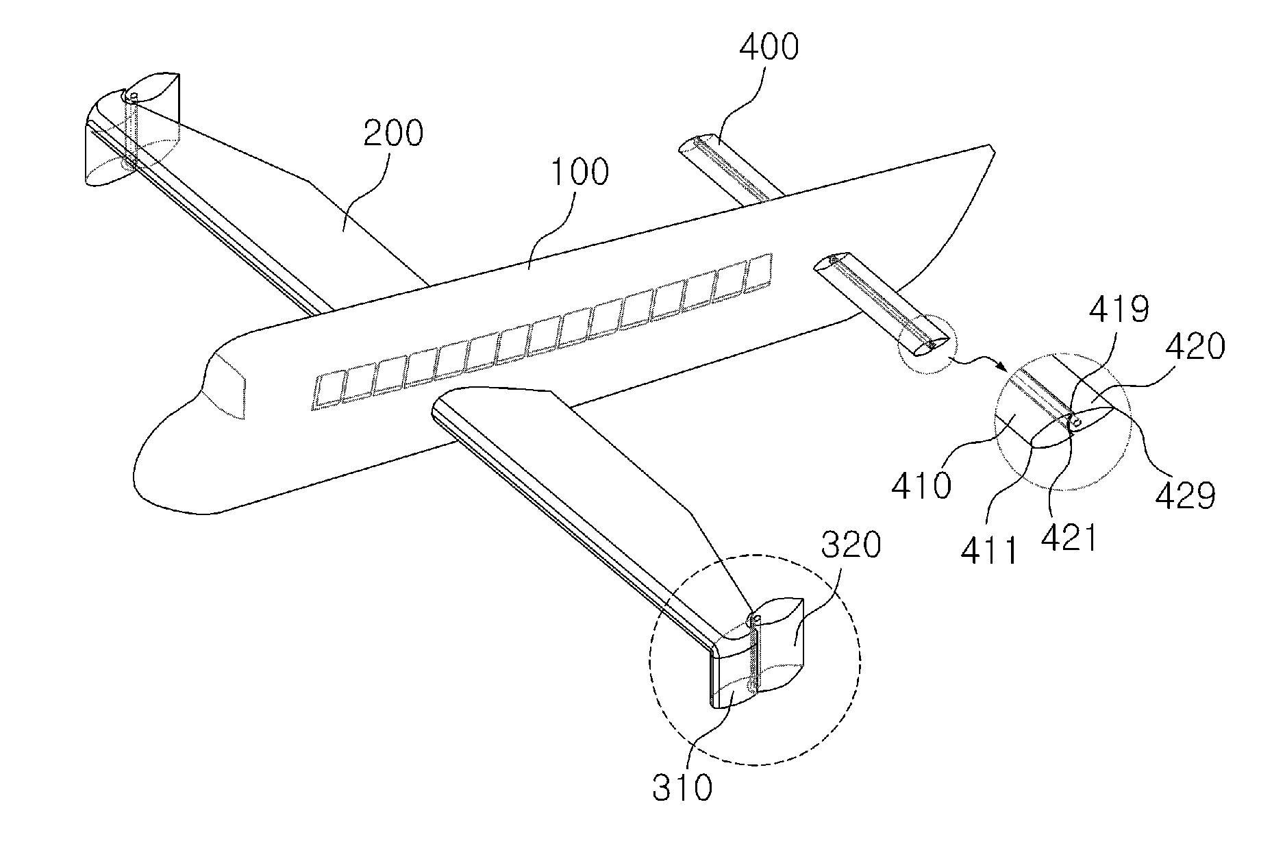
the wing structure and the configuration of the downward wing will now be described in detail with reference to FIGS. 2 to 6.

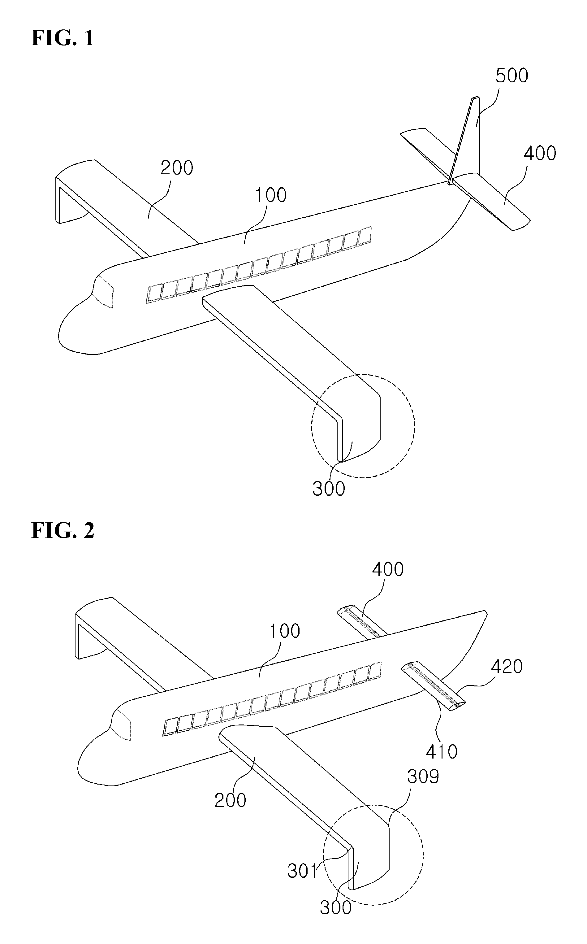
As compared to the first embodiment, in the second embodiment, the vertical tail wing is removed, the horizontal tail wing, which had been mounted to the end portion of the body of the WIG craft, is mounted at the rear side of the body that is positioned forward from the end portion, and the shape and structure of the horizontal tail wing are modified.

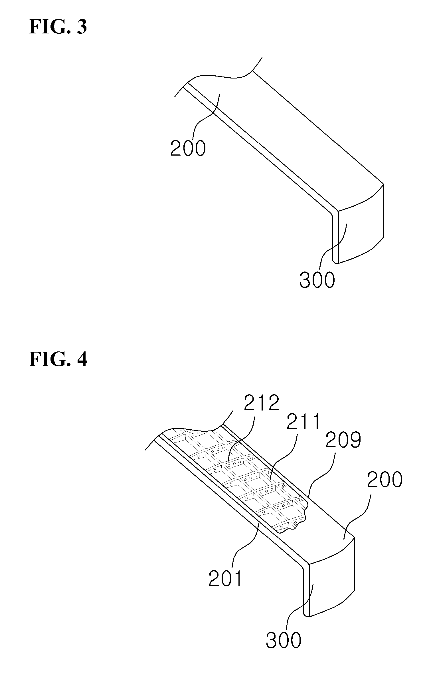
Particularly, the downward wing 300 is seamlessly connected to an end of the main wing 200 such that it extends downwards from the end of the main wing. The downward wing has a streamlined cross sectional shape in which a leading edge 301 is formed as a smooth round, and in the lengthwise direction from the leading edge 301 to the tailing edge 309, the width of the streamline increases from the vertex of the leading edge 301 to a position of between 3 / 10 and 4 / 10 of the length of the streamline, and the width of ...

third embodiment

the wing structure for a WIG craft will now be described with reference to FIGS. 7 to 11.

As shown in the drawings, the wing structure for a WIG craft includes a main wing 200 protruding outwards from the side middle portion of the body of the WIG craft, a downward wing 300 seamlessly extending vertically downwards from an outer end of the main wing 200, and a horizontal tail wing 400 extending horizontally outwards from the rear portion of the body of the WIG craft. The downward wing 300 includes a downward panel 310 integrally extending downwards from the end of the main wing 200, and a rudder unit 320 movably mounted onto a rear surface of the downward panel 310. Here, the downward wing 300, including the rudder unit 320, includes a frontal section including a leading edge 321 and a rear section including a tailing edge 329, wherein the frontal section has a round cross sectional shape with a proper thickness in order to prevent flow separation from occurring, and the rear section...

fourth embodiment

the wing structure for a WIG craft will now be described with reference to FIGS. 12 to 17.

The fourth embodiment illustrates the configuration in which while the shapes of the downward panel 310 and the rudder unit 320 are the same, the coupling structure thereof is different. That is, the vertical width of the rudder unit 320 is smaller than that of the downward panel 310, and the downward panel 310 is provided in the rear surface with a receiving groove 317 which is large enough to receive the rudder unit 320. Thus, the rudder unit 320 is mounted in the receiving groove 317 in the rear surface of the downward panel 310. In the wing structure for a WIG craft, the functions and shapes of the respective parts may be the same, so a detailed description thereof will be omitted.

As shown in FIGS. 15 and 16, the shape of the lower portion is shaped like an arch, which is a round circular shape, or a streamlined “V.” This is for upon movement of the WIG craft, maximally reducing friction wi...


PUM


Abstract

The wing structure of a WIG vehicle comprising left and right main wings, left and right downward wings, and a rudder unit. The left and right main wings protrude out from the central portions of left and right sides of the WIG vehicle. The panel of the main wing is flat and tapers successively toward the lateral edge, whereof the cross-section is airfoil-shaped and has the shape of a tadpole. The panel shaped left and right downward wings are connected with both ends of the left and right main wings without a joint and are formed heading downward to suppress vortex and guidance drag generated in both ends of the main wings. The rudder units are mounted on the rear surface of the left and right downward panels with a slight gap in order to compensate asymmetry between left and right lateral ends caused by movement under control of the fuselage driving unit of the WIG vehicle and to turn the fuselage left or right. Therefore, the wing structure of the WIG vehicle is capable of minimizing vortex and guidance drag generated in both ends of the left and right main wings by maximizing ground effect. Additionally, the wing structure has advantages for absorbing impact from the fuselage when taking off and landing and stabilizing horizontal disturbance of the fuselage because the left and right downward wings occupy much more volume than a winglet.

Description

BACKGROUND1. Field of the InventionThe invention relates, in general, to a wing structure for a WIG (wing in ground) craft and, more particularly, to a wing structure for a WIG craft in which vertical downward panels are formed seamlessly on both ends of the left and right main wings so as to suppress vortices and induced drag that are generated on both the ends of the left and right main wings, and in which asymmetry in thrust, which is between the left and right lateral ends when the WIG craft moves, is compensated under the control of a driving unit of the body of the WIG craft, thereby preventing yawing of the WIG craft and securing stability without using a vertical tail wing.2. Description of the Related ArtGenerally, aircraft use a large vertical tail wing in order to secure stability with respect to yawing and compensate for asymmetry in thrust between the left and right lateral ends. This conforms to aircraft regulations and is implemented for enabling the aircraft to opera...

Claims


Application Information

Patent Timeline
Patent Type & Authority Applications(United States)
IPC IPC(8): B60V3/06
CPCB60V1/08B64C23/065Y02T50/164B60V3/06B64C23/076Y02T50/10B63B1/16
Inventor KANG, CHANG GULEE, HAN JINLEE, CHANG MIN
Owner WING SHIP TECH
Why Eureka
Try Eureka