Pouch Machine With Sealer

a technology of sealer and pouch machine, which is applied in the field of pouch machine, can solve the problems of improper sealing, cost and complexity, and subject to wear and maintenan

Inactive Publication Date: 2011-08-25
CMD CORP
View PDF35 Cites 12 Cited by
  • Summary
  • Abstract
  • Description
  • Claims
  • Application Information

AI Technical Summary

Benefits of technology

Numerous modifications may be made to the present invention which still fall within the intended scope hereof. Thus, it should be apparent that there has been provided in accordance with the present invention a method and apparatus for making pouches that fully satisfies the objectives and advantages set forth above. Although the invention has been described in conjunction with specific embodiments thereof, it is evident that many alternatives, modifications and variations will be apparent to those skilled in the art. Accordingly, it is intended to embrace all such alternatives, modifications and variations that fall within the spirit and broad scope of the appended claims.

Problems solved by technology

The linkages in such systems are subject to wear and maintenance, as well as causing looseness in the system which could result in improper sealing.
Also, such systems require a load cell to measure the force applied by the platen, and required loss motion to control the force.
However, because this prior art patent uses force as its main control parameter, it requires an add-on force transducer and cannot rely on already available servo motor feedback, which adds cost and complexity.
Also, it teaches the use of a single servo motor, which can result in an unbalanced platen (i.e., more force on one side than the other).
Moreover, it is primarily concerned with applying sufficient force and does not recognize that the force should be controlled to prevent fracturing of the laminate film.
This design avoids the linkages of the prior art using under mounted servo motors, However, it requires two actuators (which can be expensive) to obtain the desired force, and requires space above the machine for the actuator (which moves vertically) to be mounted, and cannot be mounted beneath the machine.
However, it is sometimes desirable to change the sealing die, due to wear or to provide a different sealing profile.
In such cases the entire sealer could be changed, but that can be costly and time consuming.
Unscrewing the sealing die from the die backing member requires a tool and is time consuming.
Such clips are expensive.
Accordingly, a pouch machine that moves a platen, cross sealer, or longitudinal sealer that avoids complex linkages, applies force evenly, and is not excessively expensive is desirable.

Method used


Image

  • Pouch Machine With Sealer
  • Pouch Machine With Sealer
  • Pouch Machine With Sealer

Examples


Embodiment Construction

While the present invention will be illustrated with reference to a particular pouch machine, with particular components, it should be understood at the outset that the pouch machine can be implemented with other machines and other components

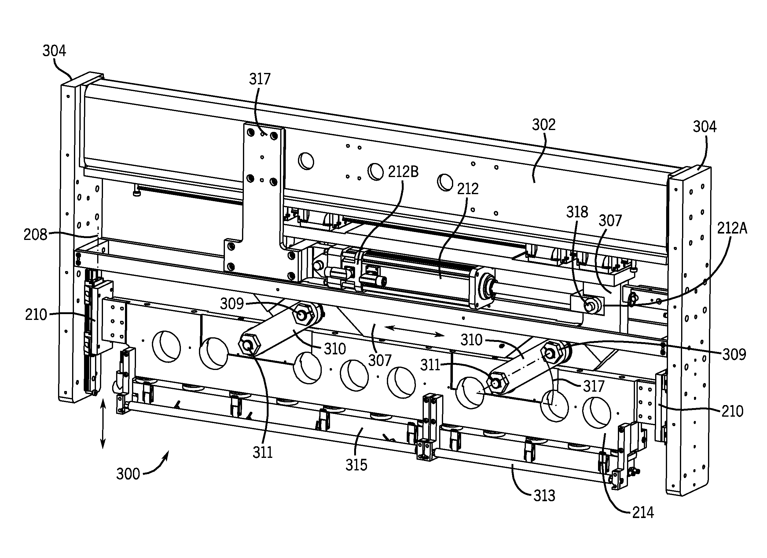
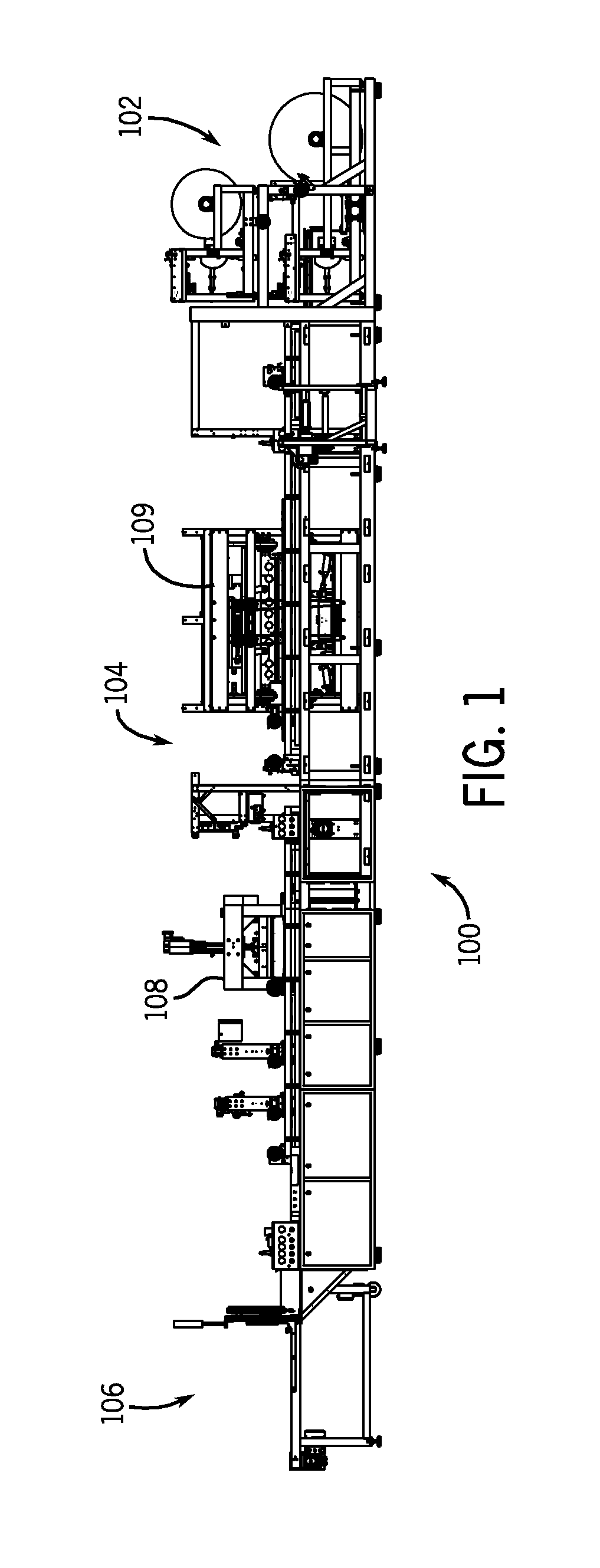
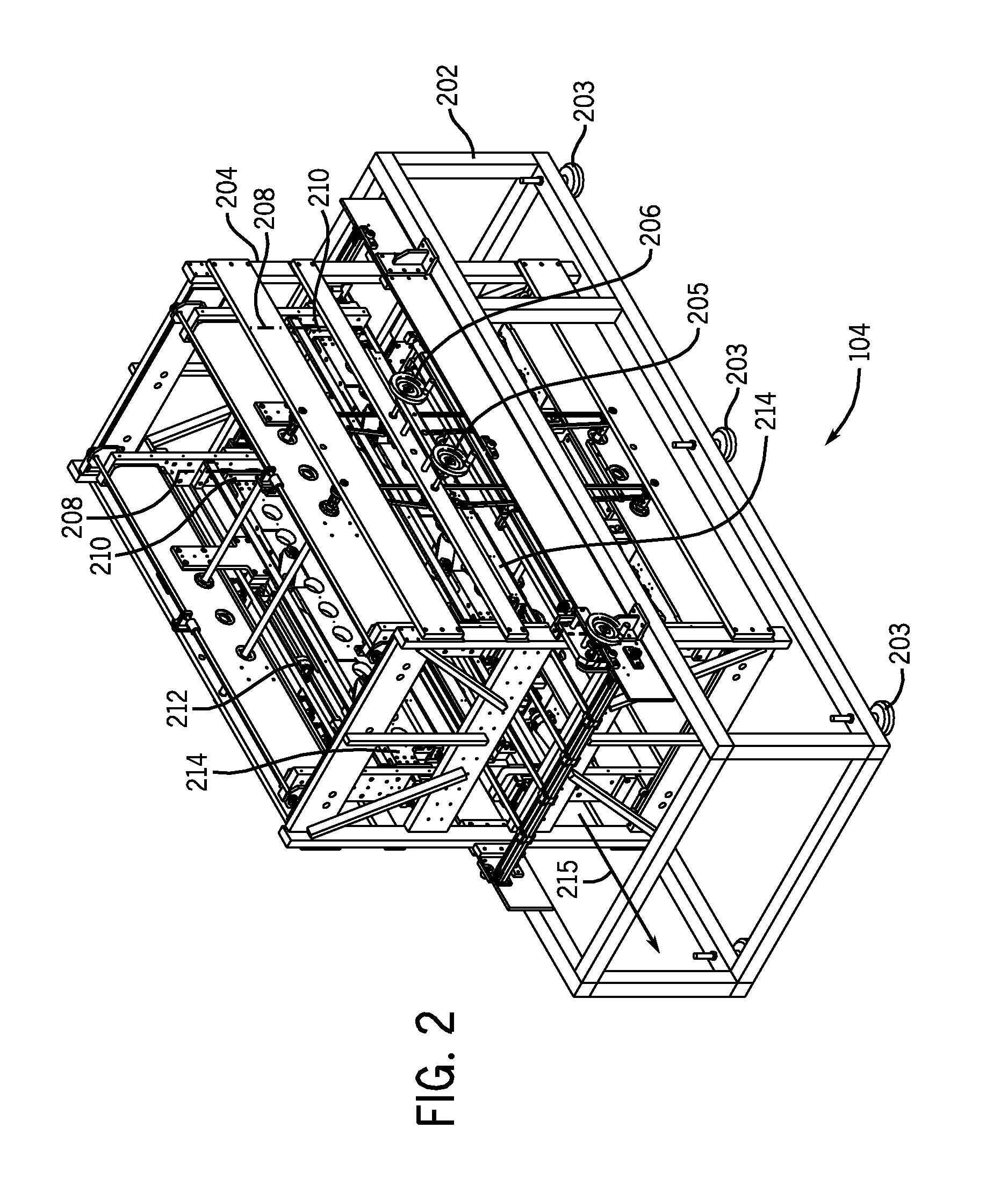
Referring now to FIG. 1, a pouch machine 100 in accordance with the present invention is shown. It includes an infeed section 102, a sealing section 104 and an outfeed section 106. Infeed section, as used herein, is a portion of the machine that receives material to be made into pouches, or partially made pouches, and transports them to a sealing section. Sealing section, as used herein, is the section of a pouch machine where one or more seals are imparted to form or partially form a pouch. Outfeed section, as used herein, is a portion of the machine that receives from a sealing section material that has been at least partially made into pouches, and transports them from the sealing section.

Infeed section 102 receives a laminate (or partially f...


PUM

PropertyMeasurementUnit
horizontal distanceaaaaaaaaaa
vertical distanceaaaaaaaaaa
torqueaaaaaaaaaa

Abstract

A pouch machine includes an infeed section, a sealing section, and an outfeed section. The infeed section provides a pouch or laminate to the sealing section, and the outfeed section receives the sealed pouch from the infeed section. The sealing section includes at least one sealer that has a sealing fixture disposed to move in a first direction toward and away from a sealing position. A linear actuator is mounted to provide a controlled motion in a second direction, that is not the first direction. A linkage is connected between the linear actuator and the sealing fixture. The linkage translates the controlled motion of the actuator into controlled motion of the sealer. The linkage preferably multiplies force when the sealer is in the sealing position, and multiplies distance / velocity when the sealer is retracted. The sealing fixture preferably includes a die backing member and a sealing die. The die backing member has at least one clip mounted on it. The clip includes a hook end, and has a first relaxed position and a second tension position. The sealing die includes at least one receiver that receives the hook end. When the clip is in the tension position, the sealing die is held against the die backing member.

Description

FIELD OF THE INVENTIONThe present invention relates generally to the art of bag making. More specifically, it relates to pouch machines, and methods of making pouches.BACKGROUND OF THE INVENTIONThere are many known machines and methods known for making bags and pouches. Intermittent motions machines are often used to make some pouches, such as those used in the medical field. Typically such medical pouches are made from a laminate film or a mono film. Laminate film, as used herein, includes a film made up of two or more layers, such as an upper layer that is sealed in various locations to a lower layer. The layers can be comprised of different materials.Generally, the prior art provides for intermittently advancing the laminate film. When the film is stationary, a sealing platen, cross sealer, or longitudinal sealer is lowered into contact with the film. Through a combination of pressure, temperature and time, an upper layer of the laminate is sealed to a lower layer. The platen typ...

Claims


Application Information

Patent Timeline
Patent Type & Authority Applications(United States)
IPC IPC(8): B31B1/64B31B23/60B31B50/64
CPCB29C65/18B29C66/1122B29C66/81469B29C66/8221B65B51/14B29C66/8511B31B23/00B31B2219/603B31B2237/00B29C66/8322B29C66/43B29C66/4312B29C66/4322B31B2160/10B31B70/00B31B70/64B31B2155/00B31B70/642B29C66/723B29L2031/7128
Inventor MORAN, DANIEL J.HUNNICUT, PETER T.
Owner CMD CORP
Why Eureka
Try Eureka