Stereoscopic flat panel display with synchronized backlight, polarization control panel, and liquid crystal display

a technology of polarization control panel and liquid crystal display, which is applied in the field of displays, can solve the problems of general lack of response time required to provide a high quality image, image that is less than ideal, and the inability of liquid crystal display to provide high quality images for complex applications, etc., and achieve the effect of rapid display of stereoscopic images

Inactive Publication Date: 2011-09-01
REAID INC
View PDF15 Cites 17 Cited by
  • Summary
  • Abstract
  • Description
  • Claims
  • Application Information

AI Technical Summary

Benefits of technology

[0007]According to one aspect of the present design, there is provided a liquid crystal display device is configured to display stereoscopic images, and comprises an LCD panel and control electronics configured to drive the LCD panel to a desired stereoscopic display state. The control electronics are configured to employ transient phase switching and overdrive the LCD panel to a desired state to enable relatively rapid display of stereoscopic images.

Problems solved by technology

The ability for liquid crystal displays to provide high quality images for complex applications, such as stereoscopic or autostereoscopic applications, is limited by the ability of the display to provide data to pixels in a very short amount of time.
Currently available displays in general do not have the response time required to provide a high quality image in stereoscopic applications, and the result is an image that looks less than ideal, particularly when transitioning from dark colors (e.g. black) to light colors (e.g. white) and vice versa.

Method used


Image

  • Stereoscopic flat panel display with synchronized backlight, polarization control panel, and liquid crystal display
  • Stereoscopic flat panel display with synchronized backlight, polarization control panel, and liquid crystal display
  • Stereoscopic flat panel display with synchronized backlight, polarization control panel, and liquid crystal display

Examples


Embodiment Construction

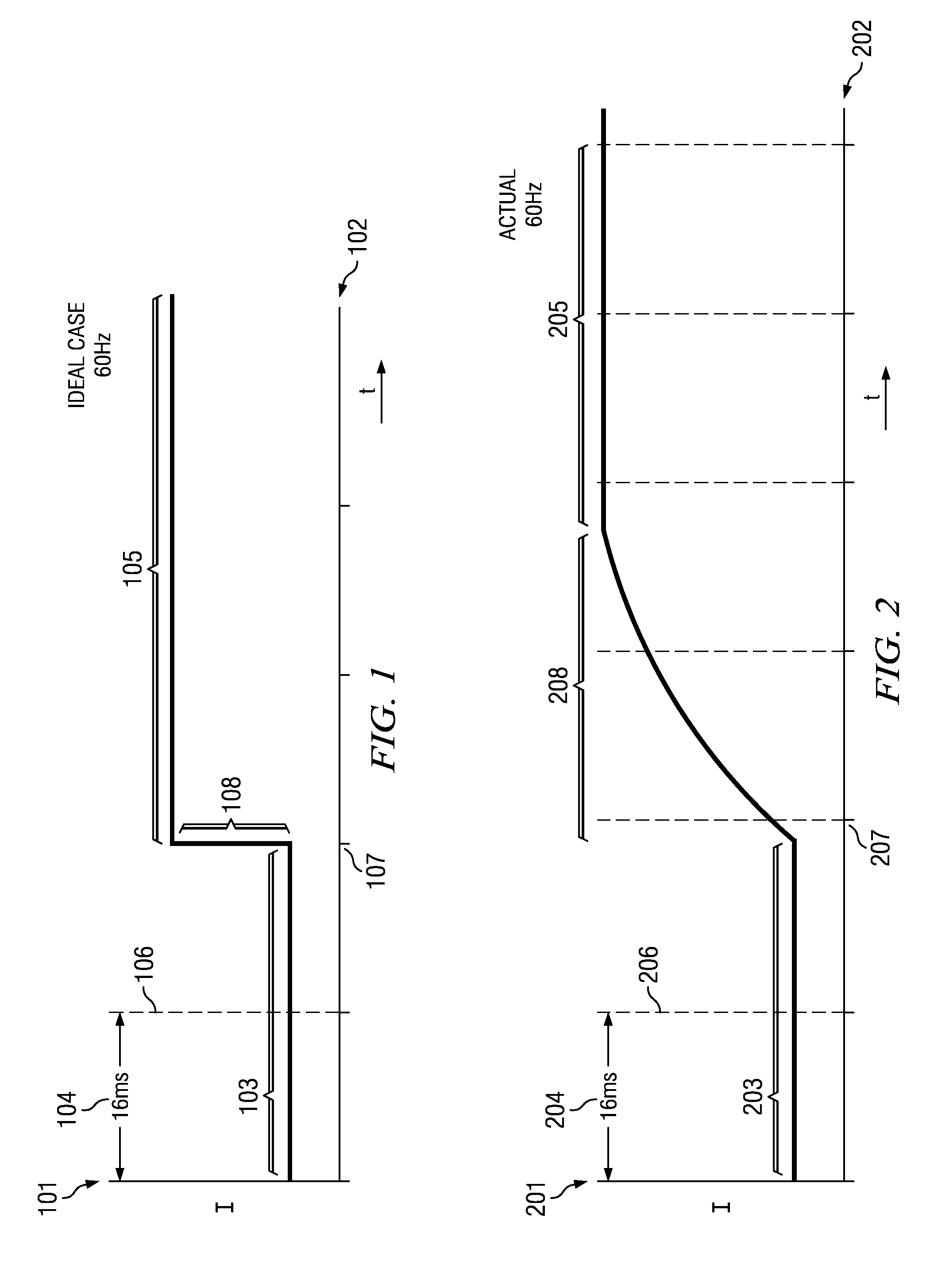
[0032]FIG. 1 represents the ideal representation of a perfect display. What we show in this drawing is the axis 101 which represents the pixel intensity, and axis 102 which represents time. In this drawing you see the dotted lines 106 and 107. Those dotted lines describe the frame update intervals. That is, every 16-millisecond interval, as noted by 104, the display is updated to show a new pixel value. In this figure, FIG. 1, we show that during the interval marked by 103 the pixel is of one value, and when the display is updated at time location 107 the pixel will assume a new value shown by the interval 105. In the ideal world, the pixel will change instantaneously as shown by the vertical slope at 108. This is an ideal case, where in an ideal “perfect-world” display a pixel will hold one value and as soon as the pixel is updated it will instantaneously go to its new value and maintain that value.

[0033]FIG. 2 shows that in a real-world implementation of liquid crystal devices, th...


PUM

PropertyMeasurementUnit
sizeaaaaaaaaaa
sizeaaaaaaaaaa
linear polarization angleaaaaaaaaaa

Abstract

An enhanced liquid crystal display design is provided having relatively fast response time particularly useful in high speed or highly intense applications, such as stereoscopic or autostereoscopic image display. The liquid crystal display device is configured to display stereoscopic images, and comprises an LCD panel and control electronics configured to drive the LCD panel to a desired 10 stereoscopic display state. The control electronics are configured to employ transient phase switching and overdrive the LCD panel to a desired state to enable relatively rapid display of stereoscopic images.

Description

CROSS-REFERENCE TO RELATED APPLICATIONS[0001]This application is a continuation-in-part and claims the benefit of U.S. patent application Ser. No. 12 / 156,683, filed Jun. 4, 2008 entitled “Display Device” which claims benefit of U.S. Provisional Patent Application Ser. No. 60 / 933,776, filed Jun. 8, 2007 entitled “Display Device,” to Joseph Chiu, et al.; this application also claims the benefit of U.S. Prov. Patent Application Ser. No. 61 / 232,346, filed Aug. 7, 2009, entitled “Liquid crystal three dimensional display,” the entirety of which are incorporated herein by reference. It should be noted that this application is being filed on Monday Aug. 9, 2010, which is the first business day following the one year anniversary of Aug. 7, 2009, pursuant to MPEP §710.05.BACKGROUND[0002]1. Field of the Invention[0003]The present invention relates generally to the art of displays, and more specifically liquid crystal displays.[0004]2. Description of the Related Art[0005]Liquid crystal displays...

Claims


Application Information

Patent Timeline
Patent Type & Authority Applications(United States)
IPC IPC(8): G02F1/1335G06T15/00G09G3/36G02B30/25
CPCG09G3/001G09G3/003G09G3/36G09G5/363G09G5/399H04N13/0497G09G2320/0252G09G2320/0261H04N13/0434H04N13/0438G09G2320/0247H04N13/337H04N13/341H04N13/398G02F1/13H04N13/00
Inventor CHIU, JOSEPHLIPTON, LENNYCOWAN, MATTARCHER, RODZIETLOW, KLAUSROBINSON, MICHAEL G.
Owner REAID INC
Why Eureka
Try Eureka