Wirelessly-chargeable stretch-resistant light-emitting or heat-emitting structure

Active Publication Date: 2011-09-08
WINHARBOR TECH CO LTD
View PDF35 Cites 379 Cited by
  • Summary
  • Abstract
  • Description
  • Claims
  • Application Information

AI Technical Summary

Benefits of technology

[0011]As such, besides being powered by the rechargeable battery, which is chargeable in a wireless fashion, for emission of heat

Problems solved by technology

During water washing, the article is stretched, twisted, and deflected and this makes the conventional way of simply attaching light-emitting structure to the article not fit, for water

Method used


Image

  • Wirelessly-chargeable stretch-resistant light-emitting or heat-emitting structure
  • Wirelessly-chargeable stretch-resistant light-emitting or heat-emitting structure
  • Wirelessly-chargeable stretch-resistant light-emitting or heat-emitting structure

Examples


first embodiment

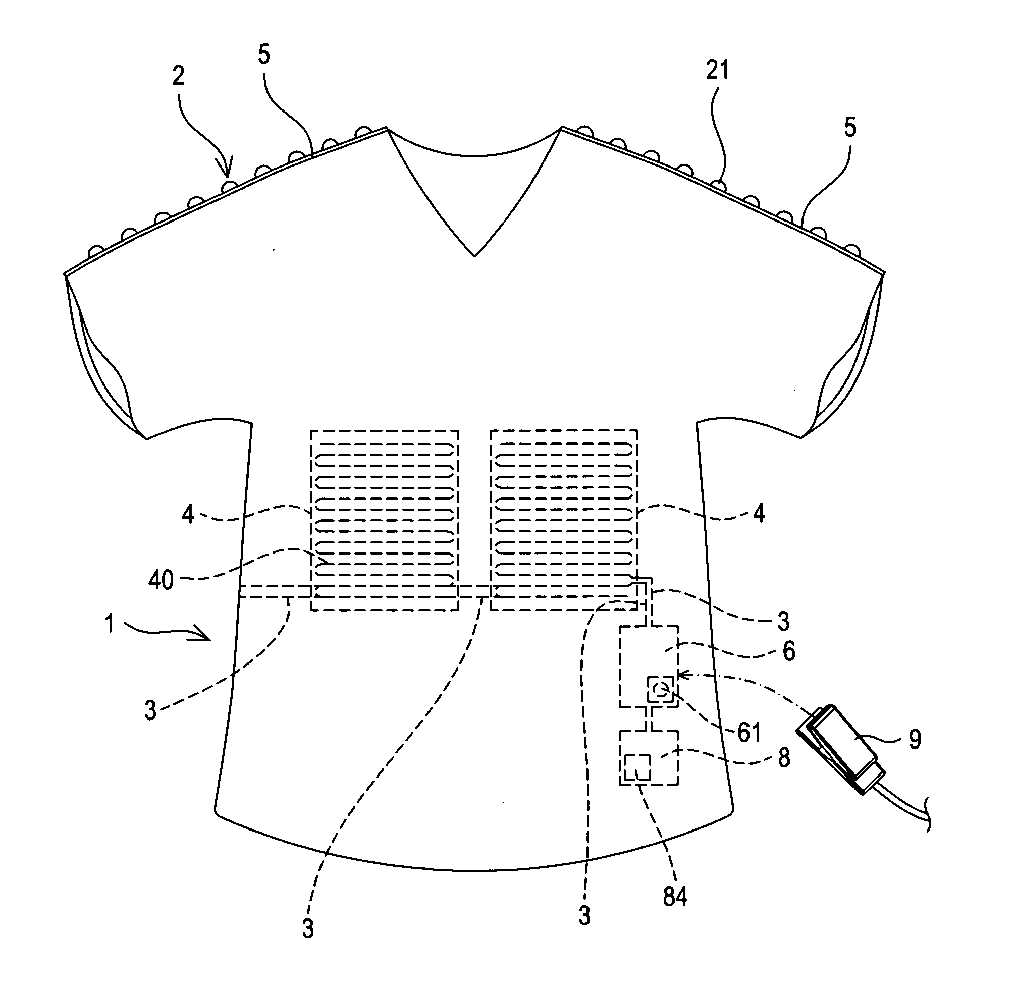
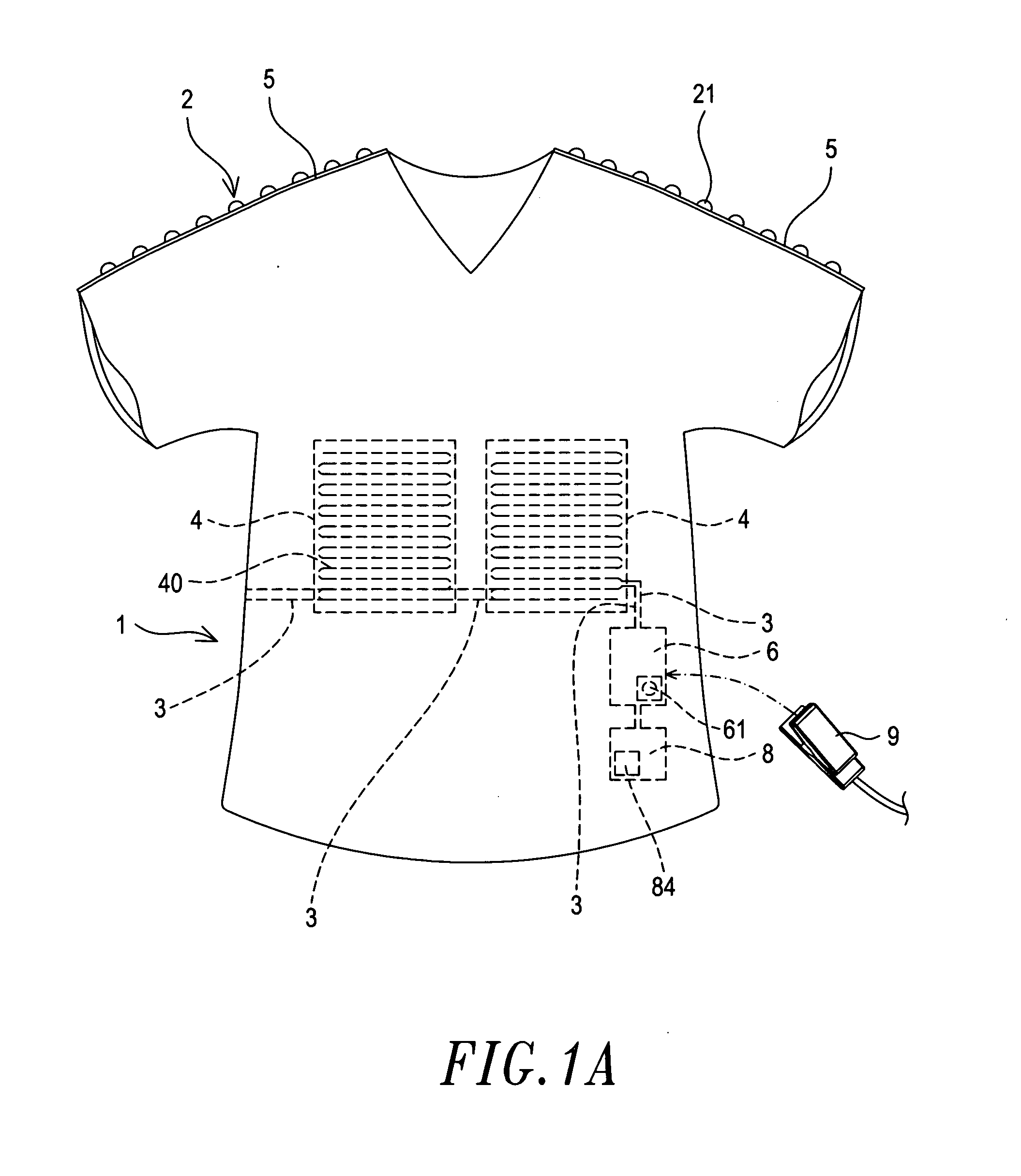
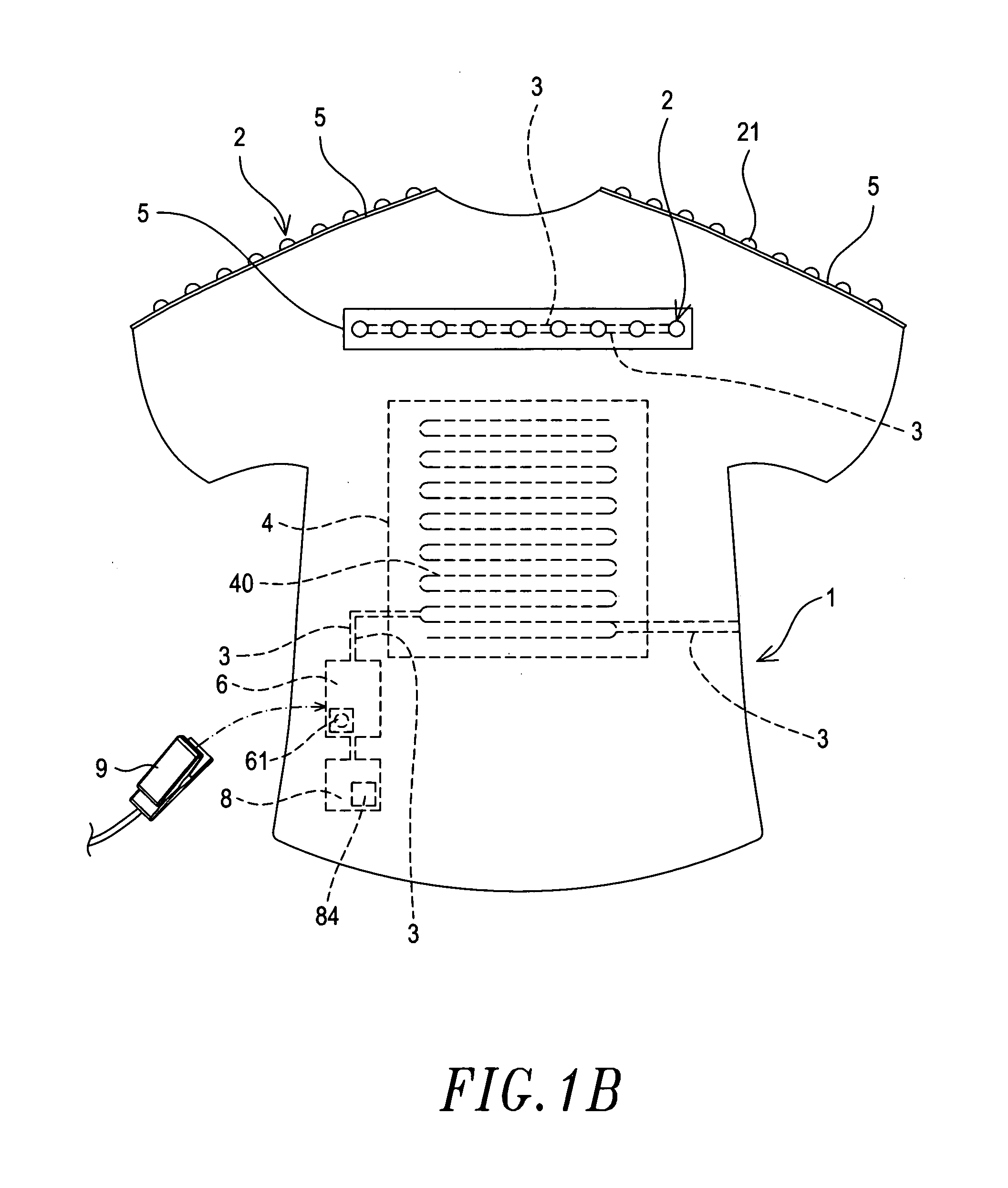
[0035]Referring to a first embodiment according to the present invention shown in FIGS. 4 and 4A, the woven member 5 is coupled to the article 1 (by means of for example sewing or being woven on or inside the article 1, the former being shown in the drawings) and is attached to the shoulders and the back of the article 1 as shown in the drawings. The conductive twisted cables 3 are woven in the woven member 5 and the light-emitting elements 2 are arranged inside the woven member 5 with the conductive pins 22 of the light-emitting element 2 being in electrical engagement with the conductive twisted cables 3 for emission of light. Light emitting from the light emission section 21 of each light-emitting element 2 is allowed to project outside the woven member 5. As shown in the drawings, the projection of light is realized through a hole formed in the woven member 5 at a location corresponding to and thus exposing the light emission section 21. Alternatively, the woven member 5 may be ...

second embodiment

[0037]Referring to a second embodiment according to the present invention shown in FIG. 4B, preferably, each of the conductive pins 22 of each light-emitting element 2 forms, in a bottom thereof, a positioning trough 221, and the positioning troughs 221 correspond respectively to the conductive twisted cables 3, whereby the conductive twisted cables 3 are respectively receivable and thus positionable in the positioning troughs 221 of the conductive pins 22. Further, the light-emitting element 2 shown in FIGS. 4A and 4B is electrically connected to two conductive twisted cables 3 with the bottoms of the conductive pins 22 respectively contacting the conductive twisted cables 3 and the conductive wires 32 of the conductive twisted cables 3 in electrical engagement with the conductive pins 22.

[0038]Referring to third and fourth embodiments according to the present invention shown in FIGS. 5 and 5A, the light-emitting element 2 is set between and in electrical connection with the two co...

fifth embodiment

[0039]Referring to a fifth embodiment according to the present invention shown in FIG. 6, each conductive pin 22 of the light-emitting element 2 forms a positioning portion 222, which in the embodiment illustrated in the drawing comprises a through hole through which the respective conductive twisted cable 3 is received and thus positioned therein, whereby the conductive twisted cables 3 are positioned in and by the positioning portions 222 of the conductive pins 22 and the conductive wires 32 of the conductive twisted cables 3 are in electrical engagement with the conductive pins 22.


PUM


Abstract

The present invention provides a stretch-resistant light-emitting or heat-emitting structure. The wirelessly-chargeable stretch-resistant light-emitting structure includes a woven member, conductive twisted cables, a light-emitting element, and a receiver circuit. The woven member is mounted to the article. Each conductive twisted cable includes a stretch-resistant wire and a conductive wire twisted together. The conductive twisted cables are woven in the woven member. The light-emitting element, which is arranged inside the woven member, includes a light emission section and two conductive pins. The conductive pins are respectively and electrically connected to the conductive wires of the conductive twisted cables. The wirelessly-chargeable stretch-resistant heat-emitting structure includes a carrying member, an electrical heating element mounted to the carrying member, conductive twisted cables that are in electrical connection with the electrical heating element, and a receiver circuit that is in electrical connection with the conductive twisted cables. The carrying member is woven in the article.

Description

FIELD OF THE INVENTION[0001]The present invention relates to a stretch-resistant light-emitting or heat-emitting structure, and in particular to a stretch-resistant light-emitting or heat-emitting structure that is wirelessly chargeable and is applicable to an article to be worn on a human body, and shows the properties of stretch resistance, pull resistance, water washability, and deflectability, and also features light emission and / or heat emission.BACKGROUND OF THE INVENTION[0002]Conventionally, to additionally mount a light-emitting structure or a heat-emitting structure to an article to be worn on a human body (such as garment, jacket, shirt, vest, underwear, pants, skirt, hat, glove, swimming suit, swimming cap, wet suit, sock, earmuffs, and bag and backpack) for emission of light or for heating purposes, the only practice that was known is to mount light-emitting elements to a jacket or a hat to improve nighttime atmosphere, amusing, or aesthetics effect.[0003]However, the ar...

Claims


Application Information

Patent Timeline
IPC IPC(8): H05B3/02F21L4/08H05B37/02H02J7/00A61F7/03
CPCA41D13/0051A41D13/01F21V23/02F21V33/0008H05B2203/036H05B3/342H05B2203/003H05B2203/014H05B2203/017F21Y2101/02F21Y2115/10F21Y2115/15H02J50/12Y10S2/905H05B1/0272
Inventor YEH, MING-HSIANG
Owner WINHARBOR TECH CO LTD
Why Eureka
Try Eureka