Moving image encoder and moving image decoder

a technology of moving image and encoder, which is applied in the direction of signal generator with optical-mechanical scanning, color television with bandwidth reduction, etc., can solve the problems of increasing the arithmetic operations of post processing, deteriorating the image quality of the picture after the scene change, and unable to use the code amount distortion characteristics of the past picture, so as to reduce image quality deterioration and circuit size, and high coding efficiency

Inactive Publication Date: 2011-09-08
MITSUBISHI ELECTRIC CORP
View PDF2 Cites 0 Cited by
  • Summary
  • Abstract
  • Description
  • Claims
  • Application Information

AI Technical Summary

Benefits of technology

[0016]According to the present invention, it is configured in such a manner that it has the separate image generating unit for producing the first separate image by sampling pixels constituting the input image at predetermined intervals, and for producing at least one second separate image by sampling pixels different from the foregoing pixels at predetermined intervals; that the intraframe predictive coding unit carries out predictive coding of the first separate image within the frame by using the pixels constituting the first separate image produced by the separate image generating unit; and that the inter-separate image predictive coding unit carries out, between the separate images, predictive coding of the second separate image produced by the separate image generating unit by using the pixels constituting the first separate image produced by the separate image generating unit. Accordingly, it offers an advantage of being able to achieve high coding efficiency by reducing image quality deterioration and a circuit size.

Problems solved by technology

Thus, the system of Patent Document 1 cannot use the code amount-distortion characteristics of a past picture when a scene change occurs.
Accordingly, it is configured in such a manner as to simply allocate the code amount equally, thereby offering a problem of deteriorating the image quality of a picture after the scene change.
In addition, since it must calculate the code amount-distortion characteristics for each separate picture as the post processing of coding, it has a problem of increasing the arithmetic operations of the post processing.
The system of Patent Document 2 has a difficulty in parallel processing because it produces separate images on a block basis of N×N pixel size, thereby offering a problem of increasing the circuit size.

Method used


Image

  • Moving image encoder and moving image decoder
  • Moving image encoder and moving image decoder
  • Moving image encoder and moving image decoder

Examples


embodiment 1

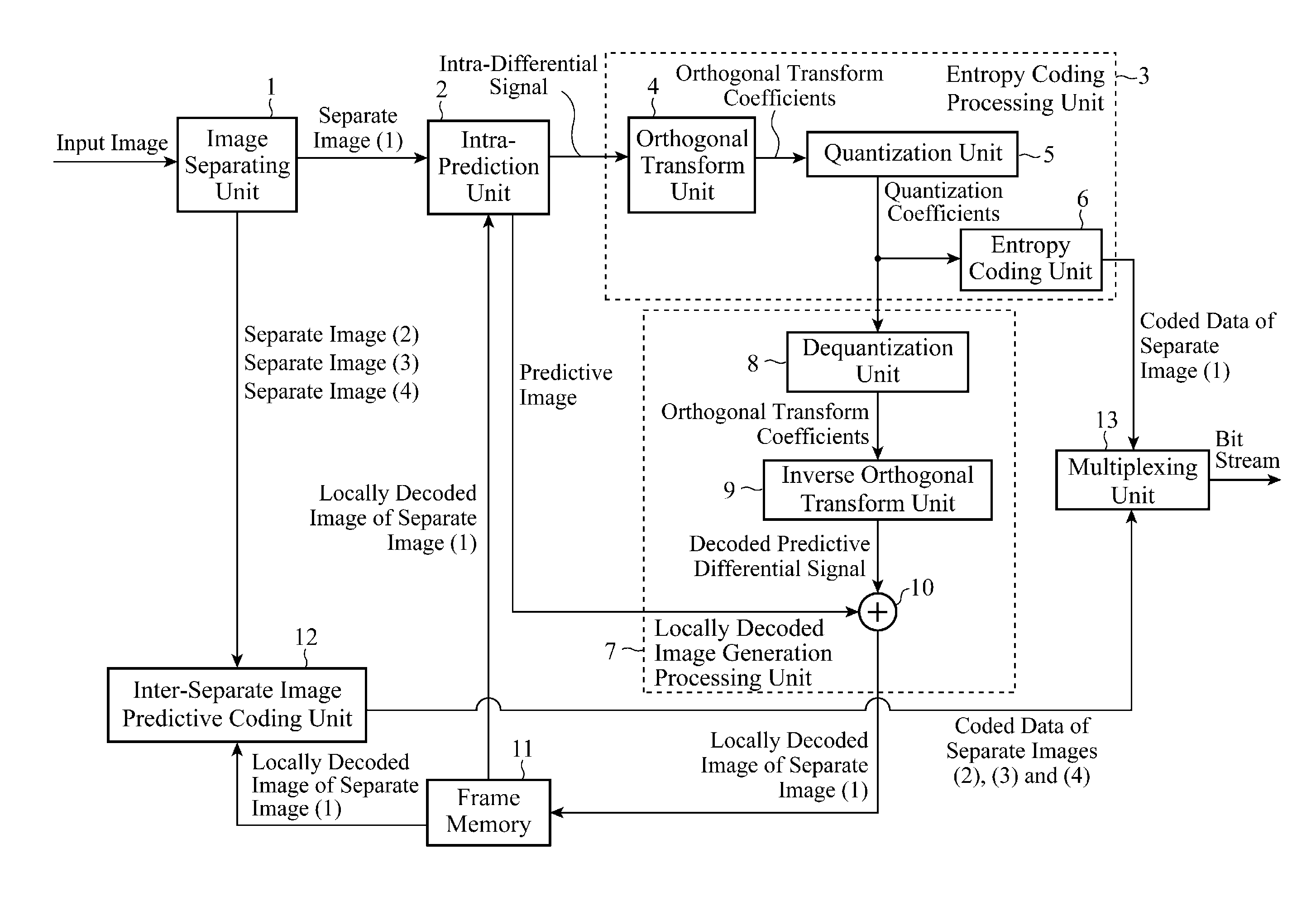
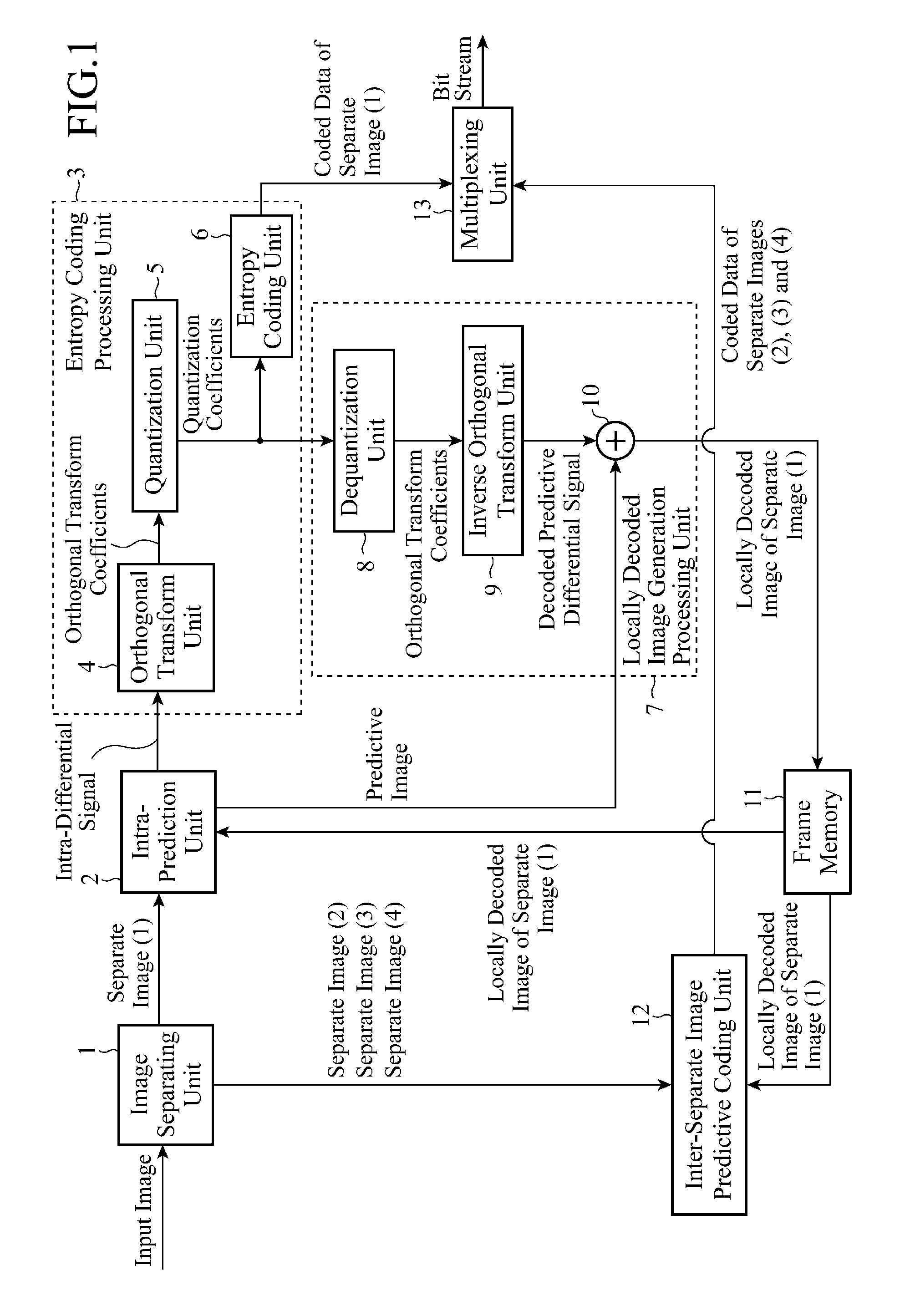
[0029]FIG. 1 is a block diagram showing a configuration of a moving image encoder of an embodiment 1 in accordance with the present invention.

[0030]In FIG. 1, an image separating unit 1 executes processing of generating a separate image (1) (first separate image) by sampling pixels constituting an input image at predetermined intervals, and of generating separate images (2)-(4) (second separate images) by sampling pixels different from the foregoing pixels at predetermined intervals. Incidentally, the image separating unit 1 constitutes a separate image generating unit.

[0031]An intra-prediction unit 2 executes processing of generating a predictive image of the separate image (1) by executing intra-prediction (intraframe prediction) of the separate image (1) produced by the image separating unit 1 on a block basis of a prescribed size, and of supplying an intra-differential signal, which represents a differential image between the separate image (1) and the predictive image, to an en...

embodiment 2

[0118]FIG. 10 is a block diagram showing a configuration of a moving image decoder of an embodiment 2 in accordance with the present invention.

[0119]In FIG. 10, a stream separating unit 31 executes processing of receiving a bit stream transmitted from the moving image encoder of FIG. 1, and of separating from the bit stream the slice data (coded data) of the separate image (1) and the slice data (coded data) of the separate images (2) (3) and (4). Incidentally, the stream separating unit 31 constitutes a coded data separating unit.

[0120]An entropy decoding processing unit 32 executes processing of decoding the intra-predictive mode and the predictive differential signal by carrying out entropy decoding of the slice data of the separate image (1) separated by the stream separating unit 31 on a block basis of the prescribed size. Incidentally, the entropy decoding processing unit 32 constitutes a first entropy decoding processing unit.

[0121]An entropy decoding unit 33 of the entropy d...


PUM


Abstract

A moving image encoder has an image separating unit (1) for generating four separate images (1)-(4) by sampling pixels constituting an input image every two alternate pixels in the horizontal direction and each alternate pixel in the vertical direction. An intraframe predictive coding unit performs intraframe predictive coding of the separate image (1) by using pixels constituting the separate image (1) produced by the image separating unit (1). An inter-separate image predictive coding unit 12 performs inter-separate image predictive coding of the separate images (2)-(4) produced by the image separating unit 1 by using the pixels constituting the separate image (1) produced by the image separating unit (1).

Description

TECHNICAL FIELD[0001]The present invention relates to a moving image encoder for separating an image into a plurality of pieces and for coding them, and to a moving image decoder for decoding an image separated into a plurality of pieces and coded.BACKGROUND ART[0002]An international standard video coding method such as “MPEG-4 AVC / H.264” (referred to as “AVC” from now on) disclosed in Non-Patent Document 1 divides an image into blocks with an N×N pixel size and performs orthogonal transform such as a DCT (Discrete Cosine Transform), quantization and entropy coding of a predictive differential signal with the N×N pixel size, which is obtained by executing intraframe / interframe predictions on a block basis.[0003]When executing predictive coding within a frame, the AVC acquires a differential signal by performing a prediction using pixels of adjacent blocks after the coding. As modes of the prediction, the total of nine modes is prepared which include an average prediction and which e...

Claims


Application Information

Patent Timeline
Patent Type & Authority Applications(United States)
IPC IPC(8): H04N7/32H04N19/593
CPCH04N19/59H04N19/593
Inventor MORIYA, YOSHIMIYAMADA, YOSHIHISASEKIGUCHI, SHUNICHIKATO, YOSHIAKI
Owner MITSUBISHI ELECTRIC CORP
Why Eureka
Try Eureka