Bridge construction and method of replacing bridges

a bridge and bridge technology, applied in bridges, bridge construction, construction, etc., can solve the problems of environmental concerns that can complicate many bridge projects, and achieve the effect of reducing the camber of beams

Inactive Publication Date: 2011-09-15
NEWTON BRIDGE SOLUTIONS
View PDF15 Cites 30 Cited by
  • Summary
  • Abstract
  • Description
  • Claims
  • Application Information

AI Technical Summary

Benefits of technology

[0004]A method for replacing a bridge forms one aspect of the invention. The bridge which may be replaced by the method is the type which includes a deck supported at its ends by a pair of spaced-apart concrete abutments, each abutment having a pair of wing walls. The method comprises the steps of: removing the deck and excavating a footing hole behind each abutment; casting a concrete footing in each footing hole; and providing a foundation pier on each footing. The method further comprises the step of providing a brace assembly and at least a pair of cambered beams. The beams are provided such that each beam spans between and is supported by the pair of piers and the beams are substantially parallel and coplanar. The br

Problems solved by technology

This is often very expensive.
Environmental concerns can complicate many bridge projects; a factor in this is that man

Method used


Image

  • Bridge construction and method of replacing bridges
  • Bridge construction and method of replacing bridges
  • Bridge construction and method of replacing bridges

Examples


Embodiment Construction

The Bridge

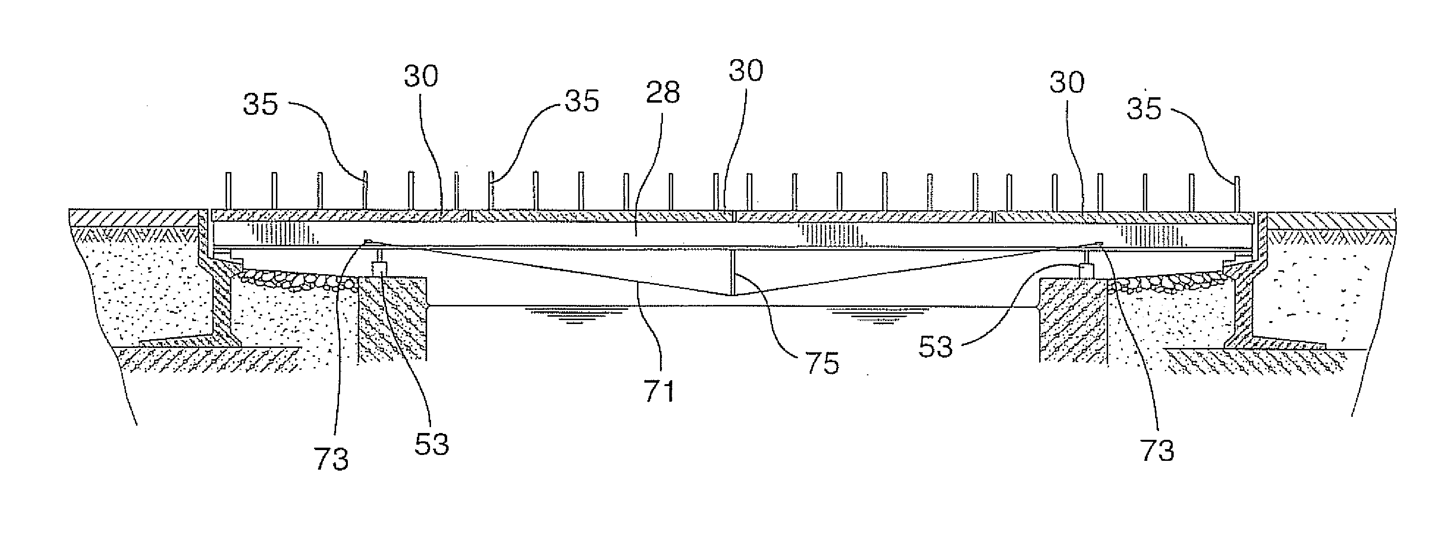
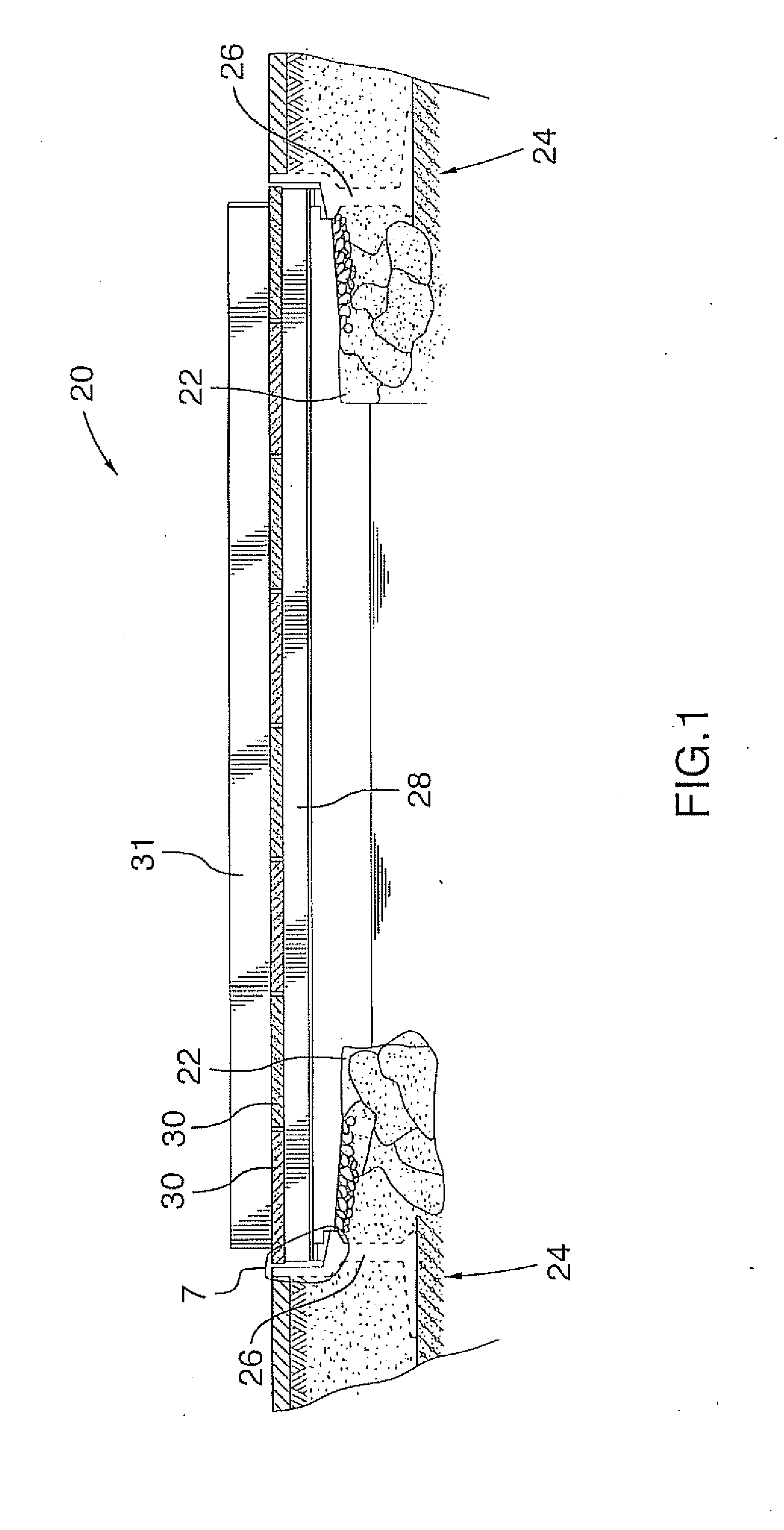
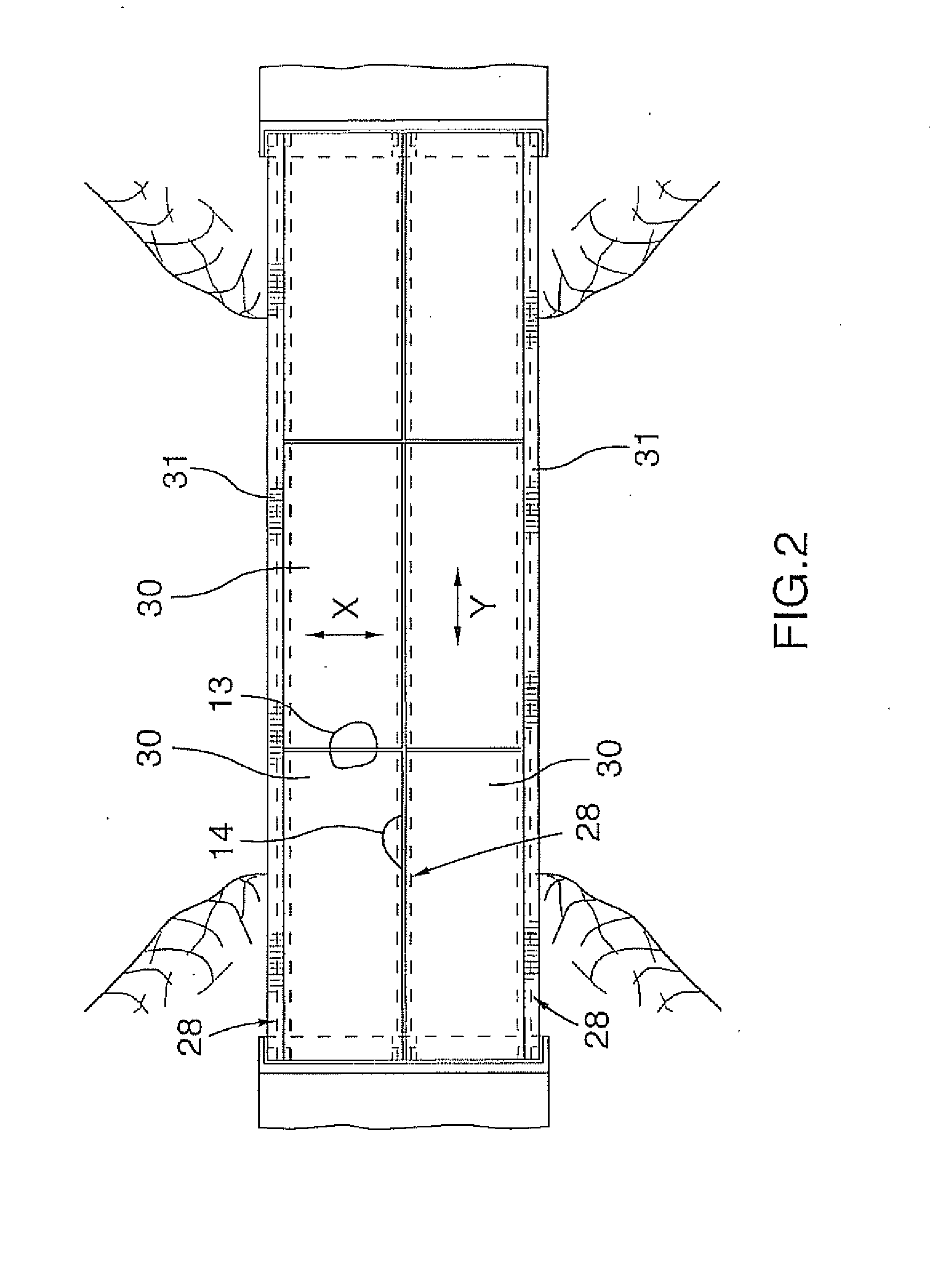
[0037]A bridge 20 according to an exemplary embodiment of the invention is illustrated in FIG. 1 and FIG. 2 and will be seen to comprise: a pair of abutments 22, a pair of footings 24, a pair of foundation piers 26, three cambered beams 28; deck elements 30; and parapet walls 31.

[0038]The abutments 22 are concrete, and spaced-apart across a watercourse.

[0039]The footings 24 are concrete, cast in situ, behind each abutment 22. Footing construction is a matter of routine to persons of ordinary skill in the art, and as such, details are neither required nor provided herein.

[0040]The piers 26 are pre-cast concrete, positioned one on each footing 24. Pier construction is a matter of routine to persons of ordinary skill in the art, and as such, details are neither required nor provided herein.

[0041]The beams 28 are substantially parallel and coplanar. Each beam 28 spans between the pair of piers 26. Parapet walls 31 are defined by pre-cast cementitious elements and also span bet...


PUM


Abstract

A bridge replacement method is disclosed. The bridge includes a deck supported by a pair of abutments, each abutment having wing walls. The deck is removed, footings are cast in holes dug behind each abutment and a pier is provided on each footing. Substantially parallel and coplanar cambered beams are provided. Each beam spans between and is supported by the piers. A brace assembly reinforces the beam camber. On each adjacent pair of beams, precast deck elements are placed, such that each element of said plurality spans the beam pair, to define at least transverse gaps between the elements and put the upper surfaces of the elements in compression in a transverse direction. The gaps are grouted. After grout curing, the brace is adjusted to reduce the beam camber and cause the upper surface of the elements to also be put into compression in a direction parallel to the beams.

Description

REFERENCE TO RELATED APPLICATIONS[0001]This application claims priority of U.S. Provisional Application 61 / 313,932 filed Mar. 15, 2010; U.S. Provisional Application 61 / 329,591 filed Apr. 30, 2010; Canadian Patent Application 2,702,546 filed Apr. 30, 2010; Canadian Patent Application ______ filed Jun. 3, 2010; and U.S. Provisional Application 61,351,589 filed Jun. 4, 2010. The contents of each of these applications are incorporated herein by reference.FIELD OF THE INVENTION[0002]The present invention relates to the field of bridge construction.BACKGROUND OF THE INVENTION[0003]Bridges need replacement from time to time. This is often very expensive. Environmental concerns can complicate many bridge projects; a factor in this is that many bridges span watercourses and many jurisdictions discourage the placement of support works in and near watercourses.SUMMARY OF THE INVENTION[0004]A method for replacing a bridge forms one aspect of the invention. The bridge which may be replaced by th...

Claims


Application Information

Patent Timeline
IPC IPC(8): E01D21/00E01D19/02
CPCE01D2/02E01D19/02E01D21/00E01D19/125E01D19/103
Inventor AUMULLER, PAUL M.NEWTON, EDKOESTER, THOMAS
Owner NEWTON BRIDGE SOLUTIONS
Why Eureka
Try Eureka