Low speed fan up camber

a gas turbine engine and fan blade technology, applied in the direction of machines/engines, liquid fuel engines, mechanical equipment, etc., can solve the problems of unsteady aerodynamic forces on the blade row itself, other aspects of engine performance may be compromised, and vibrations may decay in amplitude, so as to improve operability, reduce vibration, and increase camber

Active Publication Date: 2022-06-14
ROLLS ROYCE PLC
View PDF11 Cites 0 Cited by
  • Summary
  • Abstract
  • Description
  • Claims
  • Application Information

AI Technical Summary

Benefits of technology

[0022]The gas turbine engines and / or fan blades described and / or claimed herein (for example having the camber distributions described and / or claimed herein) may provide improved operability (for example in terms of susceptibility to flutter and / or stall) compared with conventional designs. This may allow the use of more competitive engine cycles, for example requiring less compromise for stall and flutter.
[0023]At least some of the fan blade arrangements described and / or claimed herein may be said to have increased camber in the region upstream of the covered passage. This may allow reduced camber in the covered passage region of the blade in order to achieve the same overall flow turning (or overall camber). Towards stall of the blade, this may result in the flow more closely following the blade shape towards the trailing edge and / or a healthier boundary layer towards the trailing edge, which may be better able to resist separation. This, in turn, may provide improved operability, such as improved stall margin and / or less susceptibility to flutter.

Problems solved by technology

However, in designing the engine to have optimum efficiency, the present inventors have understood that other aspects of engine performance may be compromised.
When the aerofoils in a blade row (such as the fan blades in a gas turbine engine fan) vibrate, they generate unsteady aerodynamic forces on the blade row itself.
Under most conditions, these unsteady aerodynamic forces cause the blade row to do work on the surrounding air, and the vibrations decay in amplitude.
If the work done by the air exceeds the work (for example by mechanical damping), then the vibrations will grow.
Flutter is undesirable because it can generate large stresses in an engine.

Method used


Image

  • Low speed fan up camber
  • Low speed fan up camber
  • Low speed fan up camber

Examples


Embodiment Construction

[0064]Aspects and embodiments of the present disclosure will now be discussed with reference to the accompanying figures. Further aspects and embodiments will be apparent to those skilled in the art.

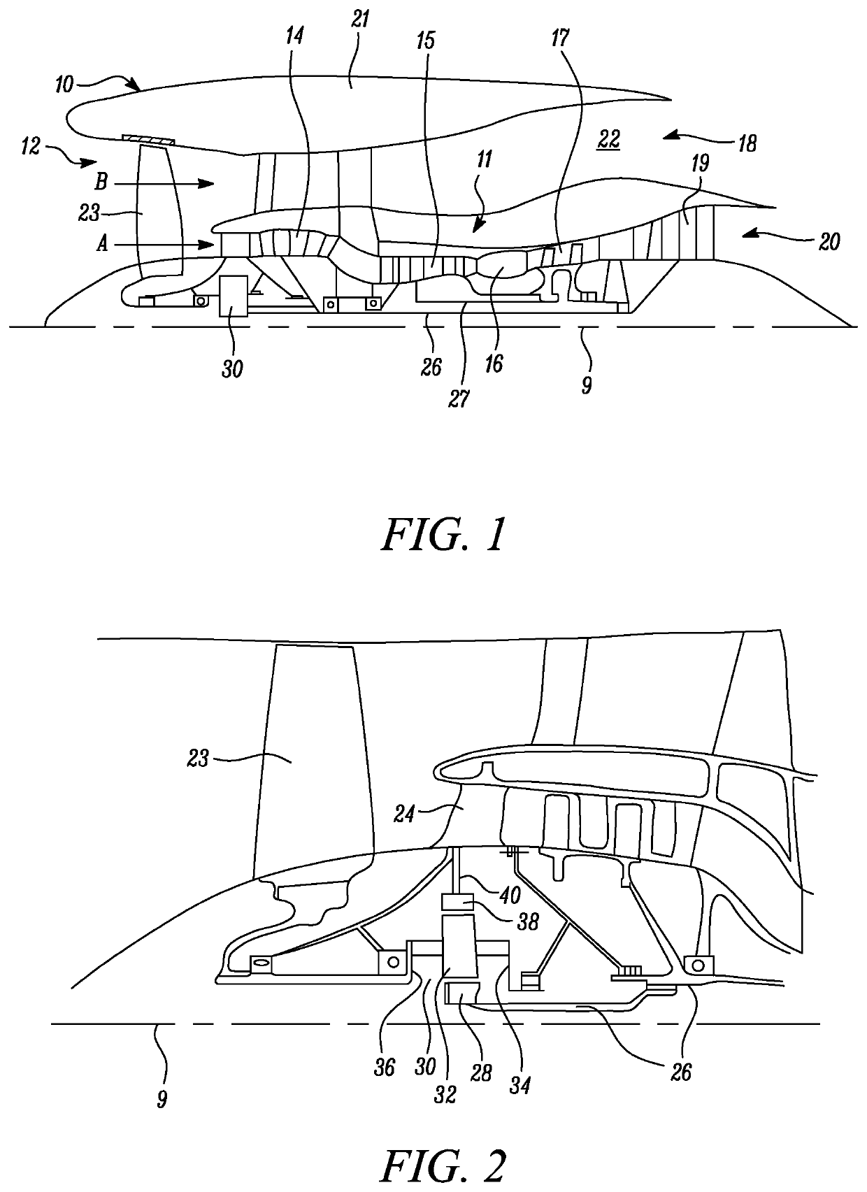
[0065]FIG. 1 illustrates a gas turbine engine 10 having a principal rotational axis 9. The engine 10 comprises an air intake 12 and a propulsive fan 23 that generates two airflows: a core airflow A and a bypass airflow B. The gas turbine engine 10 comprises a core 11 that receives the core airflow A. The engine core 11 comprises, in axial flow series, a low pressure compressor 14, a high-pressure compressor 15, combustion equipment 16, a high-pressure turbine 17, a low pressure turbine 19 and a core exhaust nozzle 20. A nacelle 21 surrounds the gas turbine engine 10 and defines a bypass duct 22 and a bypass exhaust nozzle 18. The bypass airflow B flows through the bypass duct 22. The fan 23 is attached to and driven by the low pressure turbine 19 via a shaft 26 and an epicyclic gearbox 3...


PUM


Abstract

A fan blade for a gas turbine engine has a covered passage. A cross section through the fan blade at a point along the blade span is defined as having particular change in angle (α3−α1) of the camber line between the leading edge and the trailing edge and / or between the leading edge and the point on the camber line that corresponds to the start of the covered passage.

Description

CROSS-REFERENCE TO RELATED APPLICATIONS[0001]This specification is based upon and claims the benefit from United Kingdom patent application number GB 2009933.9 filed on Jun. 30, 2020, the entire contents of which is incorporated herein by reference.BACKGROUNDTechnical Field[0002]The present disclosure relates to a fan blade for a gas turbine engine. Aspects of the disclosure relate to the camber distribution of the fan blades of a gas turbine engine.Description of the Related Art[0003]Modern gas turbine aero-engines typically comprise a fan, which compresses the incoming air and directs at least a portion of that air along a bypass duct, with the remainder of the air flowing through the engine core.[0004]Conventionally, gas turbine engines have been developed so as to provide a fan that operates a maximum efficiency when the gas turbine engine is operating at cruise conditions, because this is the condition at which the engine operates for the longest period during a flight cycle. A...

Claims


Application Information

Patent Timeline
Patent Type & Authority Patents(United States)
IPC IPC(8): F01D5/14F02K3/06
CPCF01D5/141F02K3/06F05D2220/36F05D2240/301F05D2240/303F05D2240/306F05D2250/70F05D2200/36F04D29/324
Inventor PHELPS, BENEDICT R.BARALON, STEPHANE M MWILSON, MARK J.
Owner ROLLS ROYCE PLC
Why Eureka
Try Eureka