Gas turbine engine

Active Publication Date: 2021-05-27
ROLLS ROYCE PLC
View PDF0 Cites 0 Cited by
  • Summary
  • Abstract
  • Description
  • Claims
  • Application Information

AI Technical Summary

Benefits of technology

[0030]The main fan blade may have a radial span extending from a hub at a 0% span position to a tip at a 100% span position, wherein the average camber angle of the radially innermost 10% of the radial span of the main fan blade is less than 75% of the average camber angle of the 10% portion of the radial span of the main fan blade that has the maximum average camber angle. Such a configuration may be known as decambering. Advantageously, decambering of the hub portion of the blade may reduce susceptibility to flutter of the main fan blade.
[0031]The leading edge of the auxiliary fan blade may adjoin the trailing edge of the main fan blade. Advantageously, this may reduce turbulence at the transition between the main fan blade and the auxiliary fan blade. Alternatively, the leading edge of the auxiliary fan blade may be spaced from the trailing edge of the main fan blade, i

Problems solved by technology

However, due to increased fan tip loading, the fan may be more susceptible to the self-excited vibration known as flutter.
More specifically, when the fan blades in a row of blades vibrate, they generate unsteady aerodynamic forces.
Under most conditions, these unsteady aerodynamic forces cause the blades to do work on the surrounding air, and the vibrations decay in amplitude.
If the work done by the air exceeds the work dissipated (for example by mechanical damping), then the vibrations will grow.
Such flutter is undesirable bec

Method used


Image

  • Gas turbine engine
  • Gas turbine engine
  • Gas turbine engine

Examples


Embodiment Construction

[0070]Aspects and embodiments of the present disclosure will now be discussed with reference to the accompanying figures. Further aspects and embodiments will be apparent to those skilled in the art.

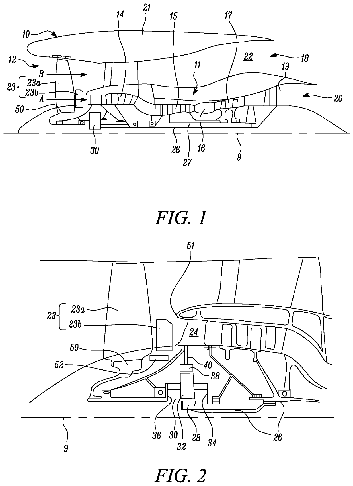
[0071]FIG. 1 illustrates a gas turbine engine 10 having a principal rotational axis 9. The engine 10 comprises an air intake 12 and a propulsive fan having a circumferential row of tandem fan blades 23 that generates two airflows: a core airflow A and a bypass airflow B. The gas turbine engine 10 comprises a core 11 that receives the core airflow A. The engine core 11 comprises, in axial flow series, a low pressure compressor 14, a high-pressure compressor 15, combustion equipment 16, a high-pressure turbine 17, a low pressure turbine 19 and a core exhaust nozzle 20. A nacelle 21 surrounds the gas turbine engine 10 and defines a bypass duct 22 and a bypass exhaust nozzle 18. The bypass airflow B flows through the bypass duct 22. The fan is attached to and driven by the low pressure turbi...


PUM


Abstract

Gas turbine aircraft engine comprising an engine core comprising a turbine, a compressor, a core shaft connecting the turbine to the compressor; and a fan upstream of the engine core and driven by the turbine, the fan comprising a circumferential row of tandem fan blades. Each fan blade comprises a main blade and an auxiliary blade. Over substantially all of the auxiliary blade's radial span, the leading edge of the auxiliary blade is rearwards of the closest point on the trailing edge of the main fan blade, and on a given aerofoil chordal section of the main fan blade, the leading edge position of an aerofoil chordal section of the auxiliary fan blade lies on a rearwards extension of the camber line of the aerofoil chordal section of the main fan blade, and the main fan blade and the auxiliary fan blade are arranged to rotate in tandem.

Description

CROSS-REFERENCE TO RELATED APPLICATIONS[0001]This specification is based upon and claims the benefit of priority from United Kingdom patent application number GB 1917171.9 filed on Nov. 26, 2019, the entire contents of which is incorporated herein by reference.BACKGROUNDField of the Disclosure[0002]The present disclosure relates to a gas turbine engine, more specifically a gas turbine engine with tandem fan blades.Description of the Related Art[0003]Modern gas turbine engines typically comprise a fan positioned upstream of an engine core, having a circumferential row of fan blades mounted onto a fan hub. The fan is driven by a turbine in the engine core to generate an air flow. A radially outer portion of the generated air flow enters a bypass duct to provide propulsive thrust. The remainder of the air flow, towards the fan hub, flows through to the engine core to power a Brayton cycle, and to provide additional propulsive thrust.[0004]In typical turbofan engines the fan is directly...

Claims


Application Information

Patent Timeline
IPC IPC(8): F02C9/22F02C7/36
CPCF02C9/22F02C7/36F05D2260/70F05D2240/60F05D2220/323F04D29/325F04D29/327F04D29/388F04D29/666F02K3/06F01D5/146F01D5/142F05D2220/36F04D29/323F01D7/00Y02T50/60
Inventor PHELPS, BENEDICT R.BARALON, STEPHANE M M
Owner ROLLS ROYCE PLC
Why Eureka
Try Eureka