Surface cleaning apparatus

a technology for cleaning apparatuses and surfaces, which is applied in the direction of suction cleaners, cleaning filter means, domestic applications, etc., can solve the problems of increasing the hand weight of the unit and the blockage of the filter with use, and achieves the effect of reducing the suction provided by the unit, enhancing the surface area, and reducing the hand weigh

Active Publication Date: 2011-09-15
OMACHRON INTPROP
View PDF16 Cites 52 Cited by
  • Summary
  • Abstract
  • Description
  • Claims
  • Application Information

AI Technical Summary

Benefits of technology

The present invention provides a hand surface cleaning apparatus which includes a pre-motor filter having improved filtration efficiency compared to existing devices. Additionally, there are various configurations wherein the pre-motor filter could overlap other parts of the device to further improve its effectiveness while maintaining lightweight design. These improvements enable extended usage times between maintenance intervals and better overall cleaning performance.

Problems solved by technology

The technical problem addressed by this patent is how to create efficient surface cleaning devices like vacuum cleaners with multiple cyclonic cleaning stages and filters to improve their performance.

Method used


Image

  • Surface cleaning apparatus
  • Surface cleaning apparatus
  • Surface cleaning apparatus

Examples


Embodiment Construction

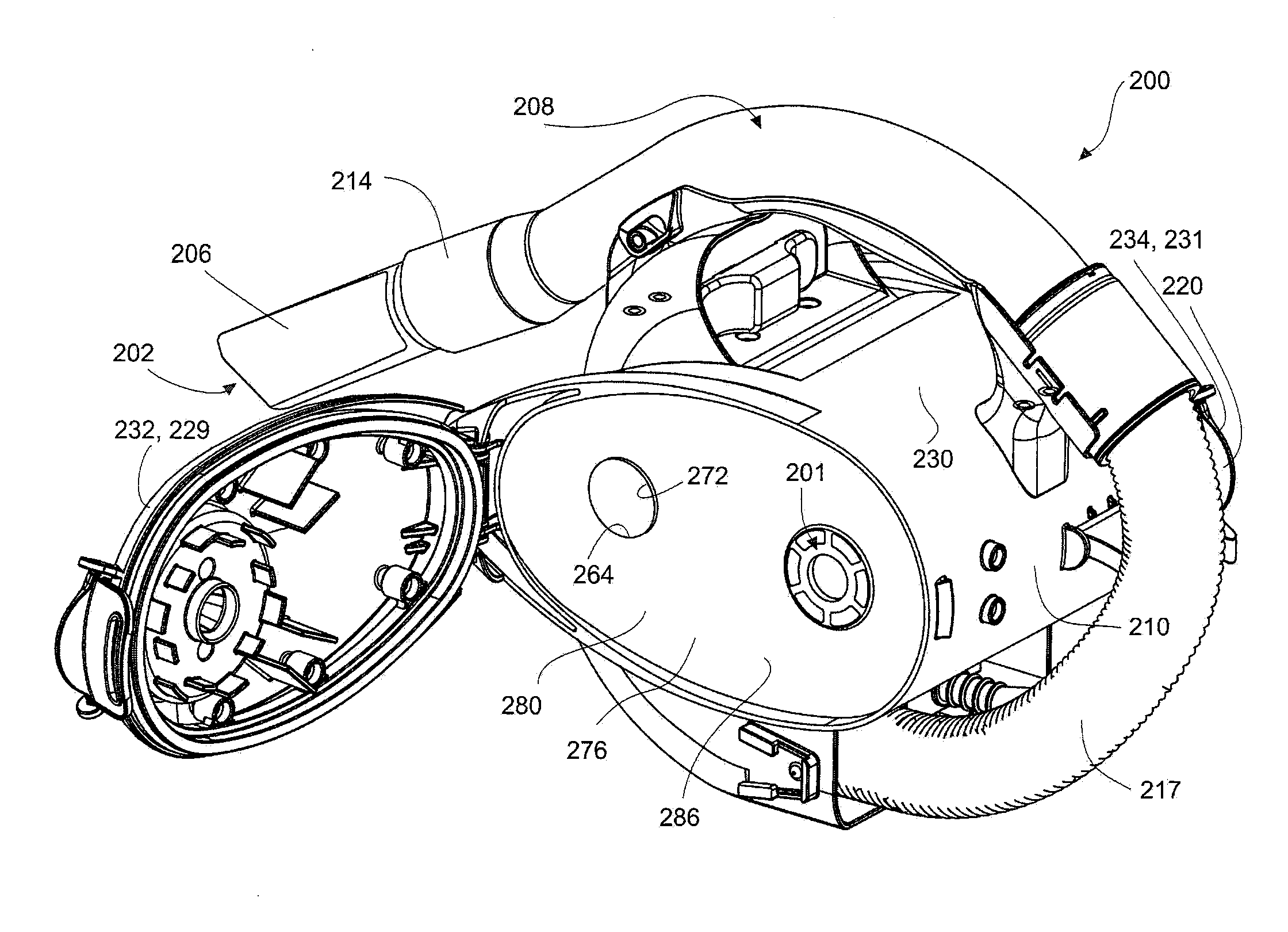
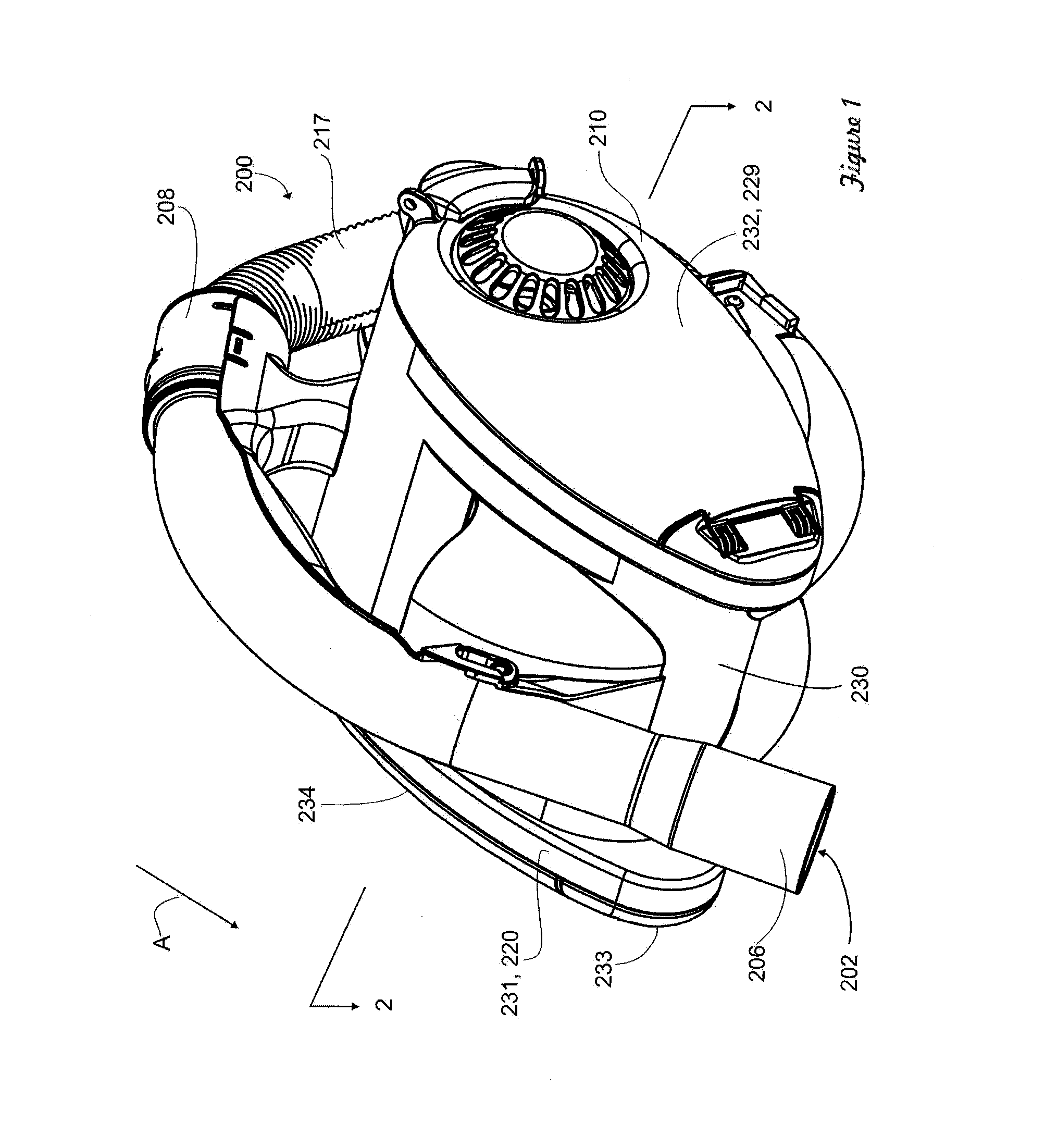
[0040]Referring to FIG. 1, an embodiment of a surface cleaning apparatus 200 is shown. In this embodiment the surface cleaning apparatus 200 is a hand operable surface cleaning apparatus. The surface cleaning apparatus 200 is usable in a forward direction of motion, indicated by arrow A in FIG. 1.

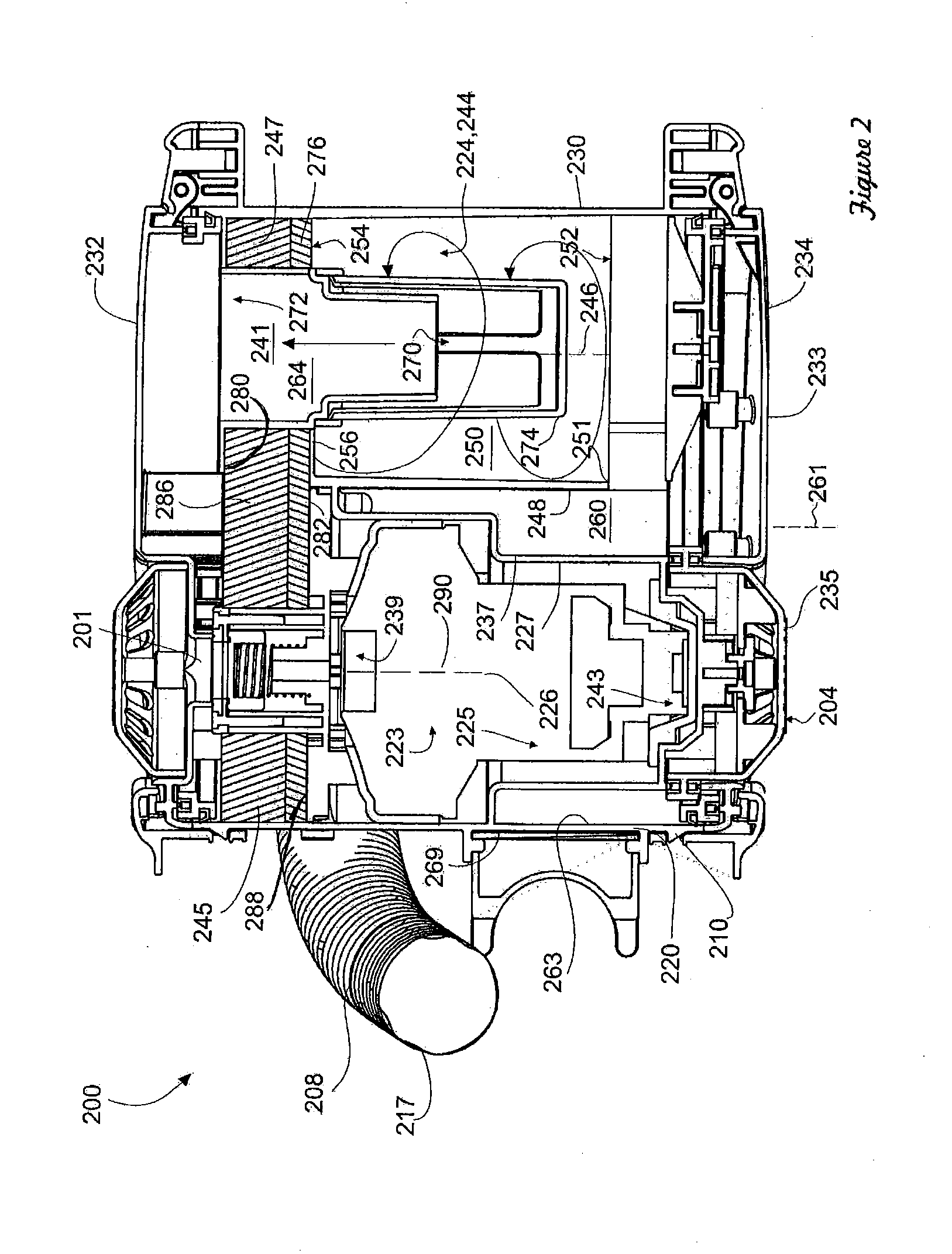
[0041]Referring to FIG. 2, the surface cleaning apparatus 200 has a dirty air inlet 202, a clean air outlet 204 (shown in FIG. 2), and an air flow passage extending therebetween. In the embodiment shown, the dirty air inlet 202 is provided in a nozzle 206. From the dirty air inlet 202, the airflow passage extends through the nozzle 206, and through an air conduit 208, to a suction and filtration unit 210. The clean air outlet 204 is provided in the suction and filtration unit 110. In the embodiment shown, the air conduit 108 includes a wand 214, and a hose 217.

[0042]Referring now to FIGS. 1 and 2, the suction and filtration unit 210 includes a main housing 220. A filtration member 224 is pr...


PUM


Abstract

A surface cleaning apparatus comprises an air flow passage extending from a dirty air inlet to a clean air outlet. A suction motor is positioned in the air flow path. At least one cyclone chamber positioned in the air flow path. An associated dirt collection chamber is optionally exterior the cyclone chamber. A pre-motor filter is positioned downstream of the cyclone chamber and upstream of the suction motor. The pre-motor filter has an upstream side and a downstream side. The pre-motor filter may overlie at least a portion of the suction motor and the cyclone chamber.

Description


Claims


Application Information

Patent Timeline
Owner OMACHRON INTPROP
Why Eureka
Try Eureka