
Image forming apparatus

Inactive Publication Date: 2011-09-15
RICOH KK
View PDF24 Cites 7 Cited by
  • Summary
  • Abstract
  • Description
  • Claims
  • Application Information

AI Technical Summary

Benefits of technology

[0015]Accordingly, embodiments of the present invention may provide a novel and useful image forming apparatus solving one or more of the problems discussed above.
[0016]In view of the above-described problems, the present invention aims at preventing a treatment liquid from dripping to the inside of the image forming apparatus when the application of the treatment liquid is not performed and also reducing the change of properties of the rollers.

Problems solved by technology

Because of this feature, such an image forming apparatus may have a drawback causing problems such as “feathering” in which each dot formed by an ink droplet spreads out in an irregular fashion (barb-like blur) and “color bleeding” in which when ink droplets having different colors are applied adjacent to each other on a sheet, the ink droplets are mixed on the boundary between the droplets, thereby causing fuzzy color boundary.
In addition, another problem is that it takes time to dry the droplets after being applied to the sheet.
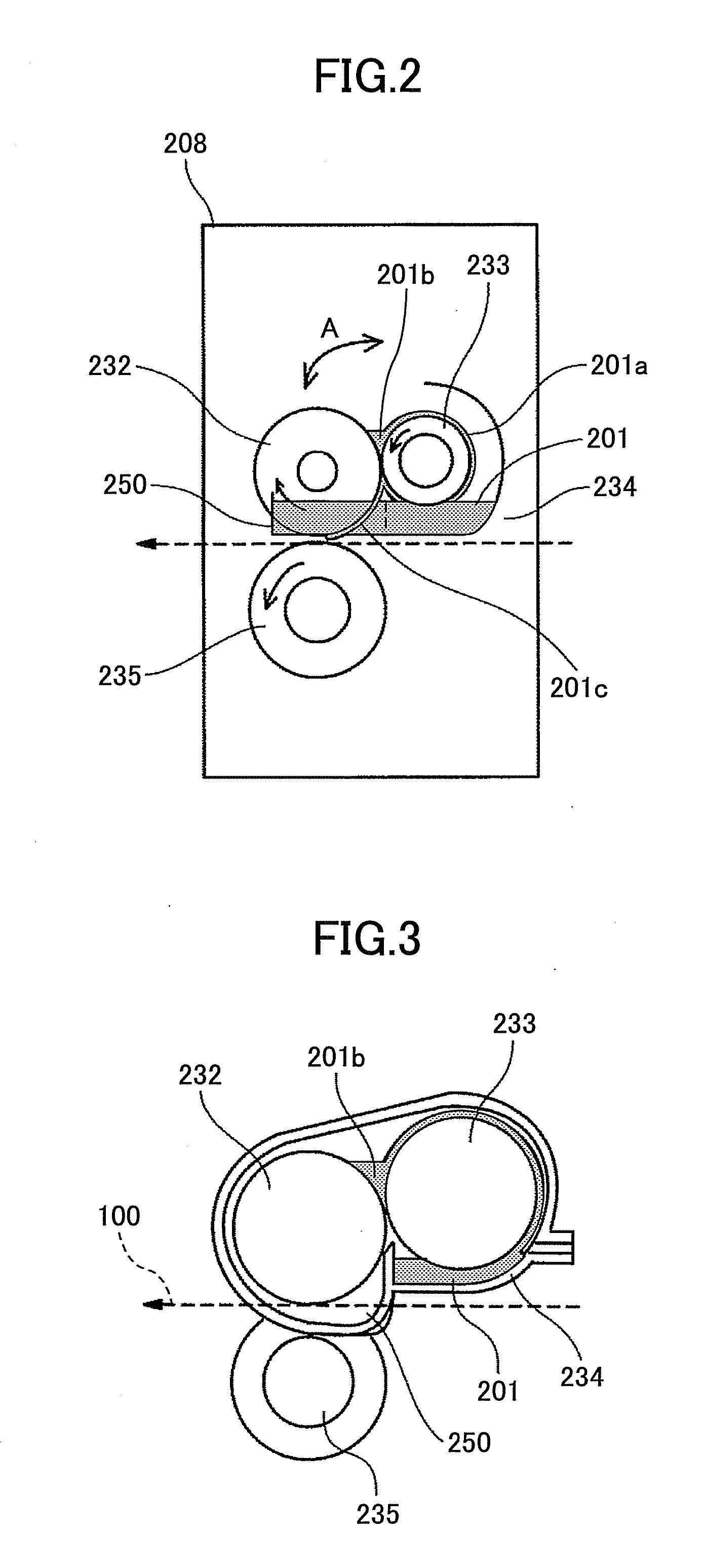
However, in the case when a treatment liquid is applied to a recording medium using a roller (application roller), the treatment liquid accumulates, at both ends of the roller, on the lateral surface of the roller, which results in ring-shaped swellings.
If the ring-shaped swellings are left over a long period of time, the treatment liquid may drip to the inside of the image forming apparatus when the roller stops rotating.
Furthermore, at the time when the application of the treatment liquid is stopped, if the application roller and a squeeze roller stop while remaining under stress, the contact portion of the rollers is kept in contact with the treatment liquid, which may result in a change of properties of the rollers.

Method used


Image

  • Image forming apparatus
  • Image forming apparatus
  • Image forming apparatus

Examples


first embodiment

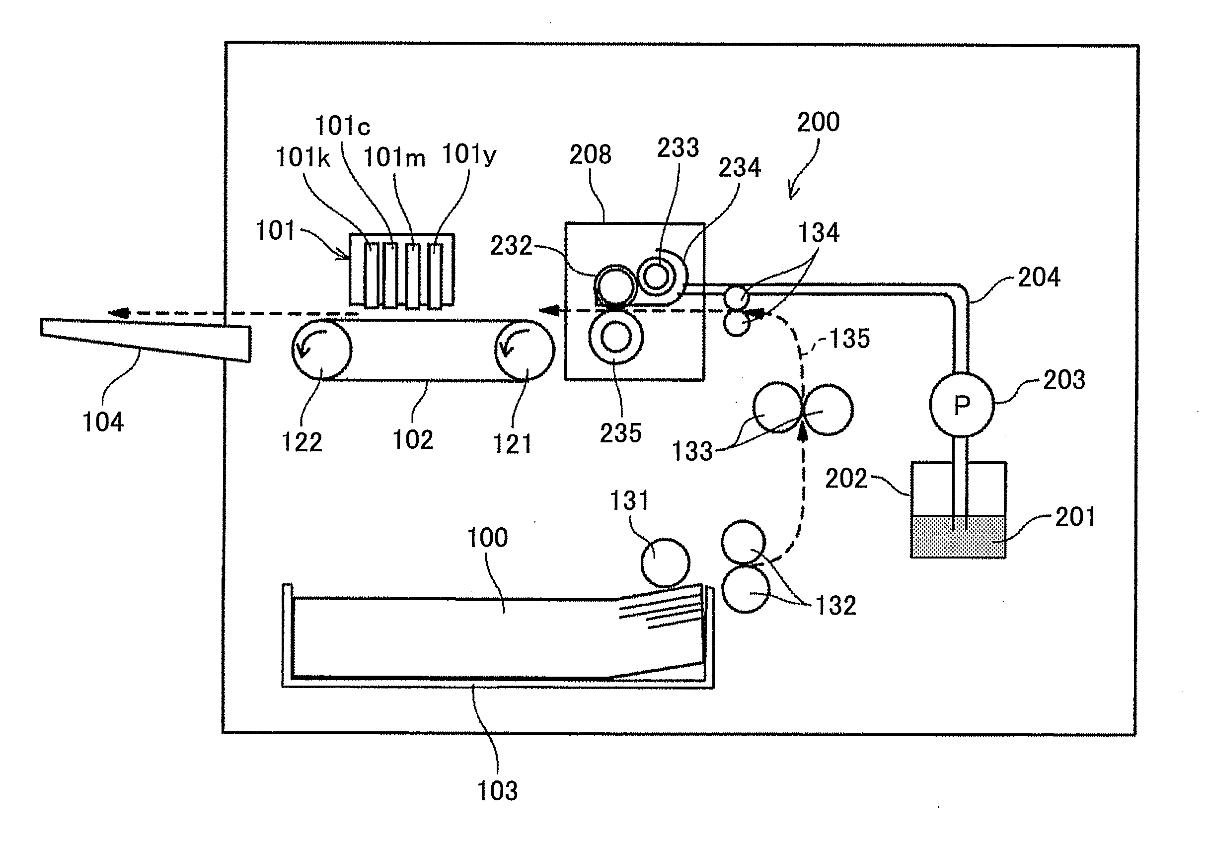
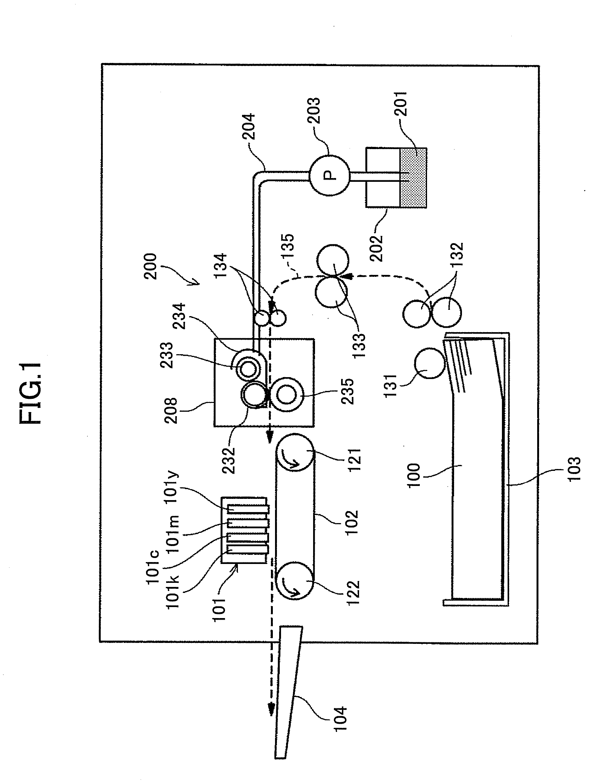
[0043]Embodiments that describe the best mode for carrying out the present invention are explained next with reference to the accompanying drawings. First, an example of an image forming apparatus according to the present invention is described with reference to FIG. 1. FIG. 1 is a diagram showing an overall structure of the image forming apparatus.

[0044]The image forming apparatus includes a recording head unit 101 configured to serve as an image forming unit for forming an image by ejecting droplets onto a sheet 100, which is a recording target medium; a conveying belt 102 for conveying the sheet 100; a sheet feed tray 103 for housing the sheets 100; and an application device 200 for applying a treatment liquid to the sheet 100, which is an application target member, on the upstream side of the recording head unit 101 in the sheet conveyance direction.

[0045]The recording head unit 101 has line-type liquid ejection heads for ejecting droplets. Each of the line-type liquid ejection ...

second embodiment

[0081]Next is described an application device according to the present invention with reference to FIGS. 9 to 12.

[0082]According to the second embodiment, a liquid supply head 240 for supplying the treatment liquid 201 is provided at the nip portion of the squeeze roller 233 and the application roller 232. The liquid supply head 240 includes a liquid inlet opening 241 which is connected to the supply channel 204.

[0083]The application roller 232, the squeeze roller 233 and the liquid supply head 240 are provided in such a manner as to integrally sway (move) to change their positions between the condition shown in FIGS. 9 and 10 (referred to as the “application condition” or “application position”) and the condition shown in FIGS. 11 and 12 (referred to as the “standby (non-application) condition” or “standby (non-application) position”. Here, these components are configured to sway together; however, the structure is not limited to this case, and for example, all the components may p...

third embodiment

[0096]The operation of the application device 200 is explained next with reference to flowcharts of FIGS. 15 and 16.

[0097]Here, in processes similar to those of the first embodiment, when the application roller 232 and the squeeze roller 233 are moved to the standby position since a subsequent request for an image output (application operation) is not received within the predetermined period of time after all the previously requested number of images are output and the rotation of the squeeze roller 233 and the application roller 232 is stopped, the squeeze roller 233 and the application roller 232 are respectively rotated for a fixed period of time in the reverse directions from their rotational directions in the application operation.

[0098]In the standby condition, since the squeeze roller 233 and the application roller 232 are vertically disposed one above the other and the valley for entrapping the treatment liquid 201 faces in the lateral direction, most of the treatment liqui...


PUM


Abstract

An image forming apparatus includes an image forming unit for forming an image on a medium; and an application device for applying a treatment liquid to the medium. The application device includes a conveying roller; an application roller for applying the liquid; a squeeze roller for reducing the thickness of the liquid on the application roller; and a tray for supplying the liquid to the squeeze roller. In the application operation, the application and squeeze rollers come in contact, and a valley formed by these rollers faces upward. In the standby condition, at least one of the application and squeeze rollers is moved to such a position that the valley faces laterally. The tray always covers the lower side of the application and squeeze rollers in regions near the longitudinal end portions of the application roller, which end portions do not come in contact with the conveying roller.

Description

CROSS-REFERENCE TO RELATED APPLICATIONS[0001]This patent application is based upon and claims the benefit of priority of Japanese Patent Application No. 2010-056819 filed on Mar. 13, 2010 the entire contents of which are incorporated herein by reference.BACKGROUND OF THE INVENTION[0002]1. Field of the Invention[0003]The present invention is generally directed to an image forming apparatus, and in particular to an image forming apparatus equipped with a device for applying a treatment liquid.[0004]2. Description of the Related Art[0005]Among image forming apparatuses such as printers, facsimile machines, copiers, plotters and multifunction peripherals having the aforementioned functions, there are liquid jet recording image forming apparatuses including, for example, a recording head for ejecting ink droplets. Such a liquid jet recording image forming apparatus is capable of ejecting ink droplets from its recording head onto a sheet being conveyed to form an image on the sheet. It is...

Claims


Application Information

Patent Timeline
IPC IPC(8): B05C1/00B05C9/12B05C11/11B05C13/00
CPCB41J11/0015
Inventor KITAOKA, SATOSHIMATSUMOTO, KAZUYOSHIIMOTO, SHINJISHIBUYA, KAZUTO
Owner RICOH KK
Learn More