Image forming apparatus, image forming system, and image density adjustment method

a technology of image density and forming system, applied in the direction of electrographic process apparatus, instruments, optics, etc., can solve the problems of inability to accurately correct gradation, measure density at shorter intervals, etc., and achieve the effect of correcting density unevenness

Inactive Publication Date: 2011-09-15
KONICA MINOLTA BUSINESS TECH INC
View PDF5 Cites 3 Cited by
  • Summary
  • Abstract
  • Description
  • Claims
  • Application Information

AI Technical Summary

Benefits of technology

[0008]In order to solve at least one problem mentioned above, according to an aspect of the present invention, an image forming apparatus which forms a test pattern including a belt-shaped pattern, the image forming apparatus includes: an image forming section which forms the belt-shaped pattern on a sheet, the belt-shaped pattern which has a prescribed length extending in a main-scanning direction, and of which a density is measured at prescribed measurement-distance intervals starting from a measurement starting position corresponding to a formation starting position of the belt-shaped pattern; and a control section which allows the image forming section to form the belt-shaped pattern on a plurality of sheets in such a way that the formation starting position of the belt-shaped pattern is shifted for a distance in the main-scanning direction sheet by sheet, the distance which is obtained by dividing the measurement-distance by a number of sheets on which the belt-shaped pattern is to be formed; col

Problems solved by technology

However, even when an attempt is made to improve the accuracy of the gradation correction by increasing the number of measurement positions, the image forming apparatuses described in the Japanese Patent Application

Method used


Image

  • Image forming apparatus, image forming system, and image density adjustment method
  • Image forming apparatus, image forming system, and image density adjustment method
  • Image forming apparatus, image forming system, and image density adjustment method

Examples


Embodiment Construction

[0029]Hereinafter, an embodiment of the present invention is described in detail referring to the accompanying drawings. However, the scope of the present invention is not limited to the drawings.

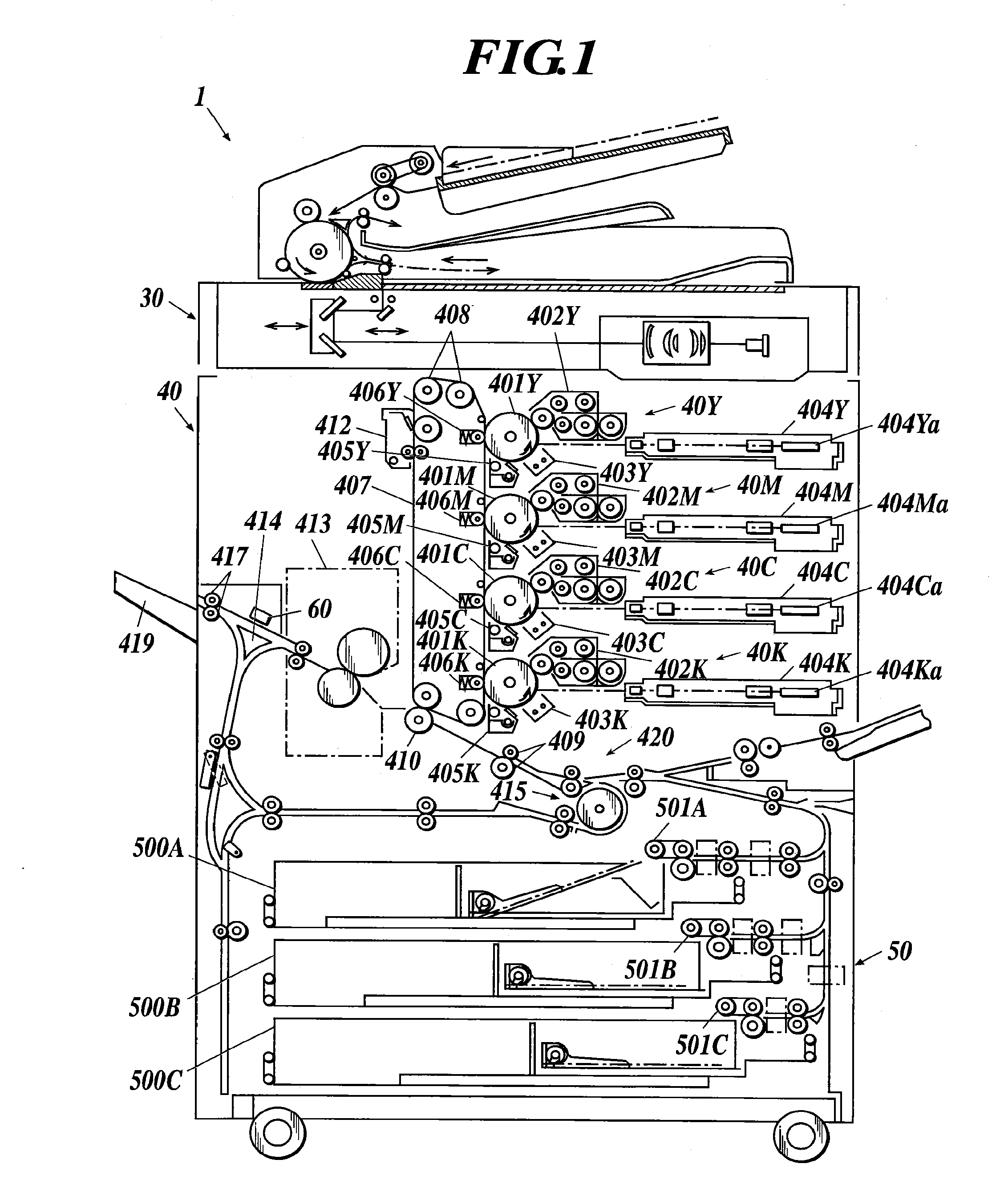
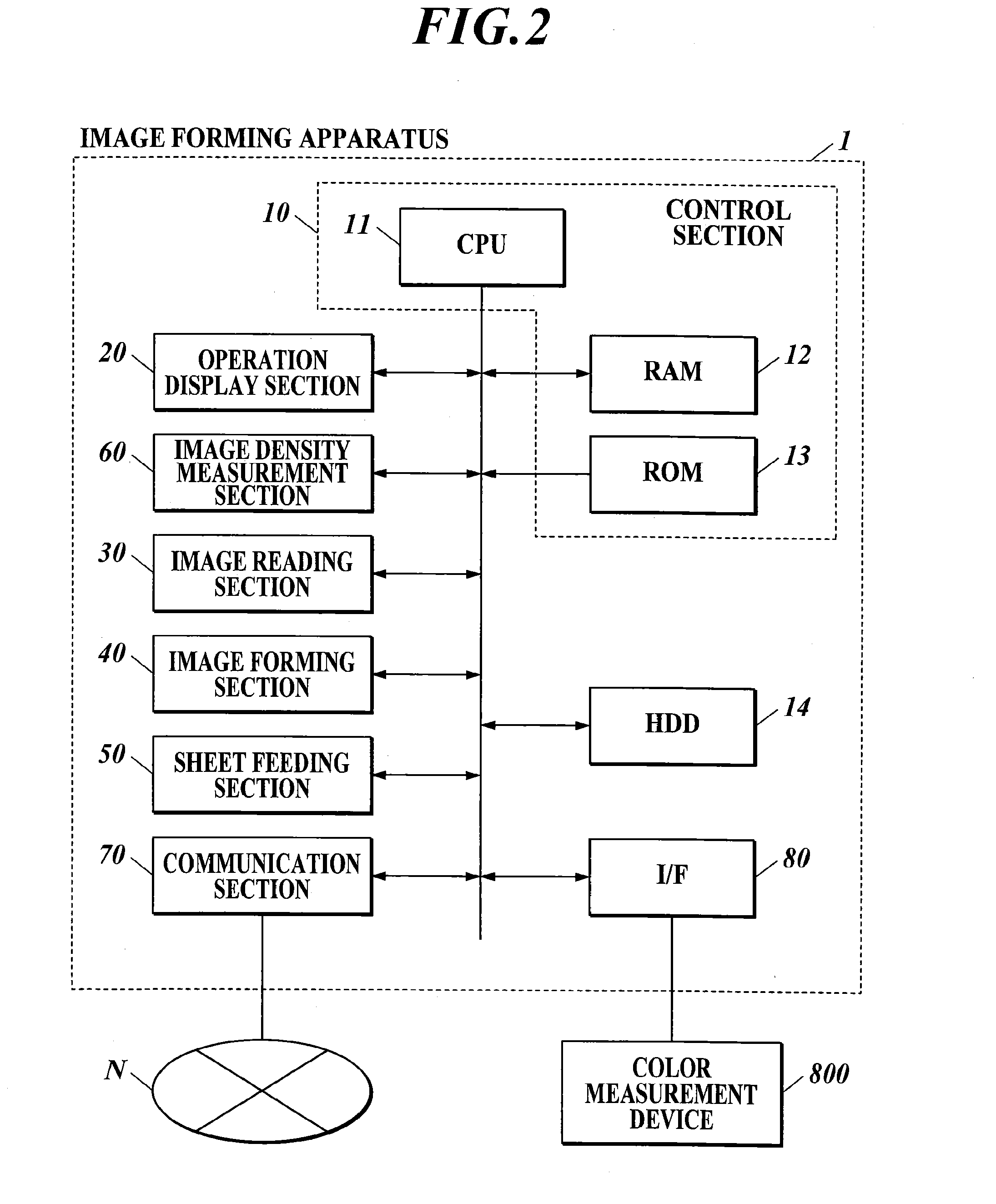
[0030]An image forming apparatus 1 includes an image reading section 30, an image forming section 40, a sheet feeding section 50, and an image density measurement section 60 as shown in FIG. 1, for example.

[0031]The image reading section 30 includes an auto document feeder (ADF), a platen glass, a charge coupled device (CCD), and a light source. Light is emitted from the light source so as to irradiate a document which is supplied by the ADF or set at a prescribed position, and thereby the document is scanned. The CCD performs photoelectric conversion of reflected light of the light. Consequently, the image reading section 30 reads an image on the document as red (R), green (G), and blue (B) analog image signals, converts the read analog image signals into image data of R, G, and B, and out...


PUM


Abstract

An image forming apparatus including: an image forming section; and a control section allowing the image forming section to form a belt-shaped pattern on sheets in such a way that a formation starting position of the belt-shaped pattern is shifted for a distance, obtained by dividing a measurement-distance by a number of sheets to be used, in a main-scanning direction sheet by sheet; collecting, sheet by sheet, pieces of density information each of which indicates the density of the belt-shaped pattern at a measurement position of measurement positions; creating data in which the pieces of density information respectively correspond to the measurement positions arranged in the main-scanning direction on each of the sheets; and correcting density unevenness of image data in the main-scanning direction based on the created data, wherein the image forming section forms an image based on the image data of which the density unevenness is corrected.

Description

BACKGROUND OF THE INVENTION[0001]1. Field of the Invention[0002]The present invention relates to an image forming apparatus, an image forming system, and an image density adjustment method.[0003]2. Description of the Related Art[0004]In a conventional electro-photographic image forming apparatus, density unevenness is produced in a main-scanning direction by various factors such as distortion and dirt of an electrifier which electrifies a photoreceptor, distance deviation between the photoreceptor on which a latent image is formed and a developing roller which is used for developing the formed latent image by developer such as toner, and difference of an amount of the developer carried by the developing roller.[0005]To solve the problem, there is known a conventional image forming apparatus which outputs patches in various forms, and corrects a gradation based on values obtained by measuring the density of the patches, as described in Japanese Patent Application Laid-open Publicatio...

Claims


Application Information

Patent Timeline
IPC IPC(8): G03G15/00
CPCG03G2215/00067G03G15/5062
Inventor SAKATANI, KAZUOMI
Owner KONICA MINOLTA BUSINESS TECH INC
Why Eureka
Try Eureka