Density correction profile generation method and image forming device

a density correction and image technology, applied in the field of density correction profile generation method and image forming device, can solve the problems of noise may be superimposed on the image signal, and the density unevenness in the image due to variations in the ink discharge characteristics of high frequency components cannot be sufficiently eliminated, so as to correct density unevenness in the printed image

Active Publication Date: 2020-09-01
RISO KAGAKU CORP
View PDF6 Cites 0 Cited by
  • Summary
  • Abstract
  • Description
  • Claims
  • Application Information

AI Technical Summary

Benefits of technology

[0012]In such a case, when the density gradation value of pixels corresponding to the respective nozzles is corrected by the density correction value calculated from the synthesized image signal, an unnatural density difference is generated between a pixel corresponding to the connection portion of the high-frequency band of the image signal as the reading result by the scanner and other frequency bands and surrounding pixels thereof. The density difference generated between the pixel corresponding to the connection portion and the surrounding pixels thereof prevents the density unevenness in an image formed on the recording medium from being appropriately eliminated.
[0015]The present invention has been made in view of such conventional problems. It is an object of the present invention to provide a density correction profile generation method that can generate, with appropriate contents, a density correction profile that corrects density unevenness in a printed image caused by variations in the recording characteristics present between recording elements of a recording head at the time of recording an image on a recording medium by the recording elements, and an image forming device suitable for being used at the time of printing an image by using the density correction profile generated by the generation method.Solution to Problem

Problems solved by technology

In the inkjet recording device, if there are variations in ink discharge characteristics among the respective nozzles, density unevenness is generated in an image due to the size or displacement of positions of dots formed on a recording medium such as printing paper.
However, when the test pattern image is to be read by the scanner, noise may be superimposed on an image signal, for example, because dark color fiber mixed into the printing paper or dirt on a glass placing table on which an original document to be read is placed is read together with the test pattern image.
If the variations in the high frequency components of density are included in the image signal as the reading result of the test pattern image by the scanner, even if the density gradation values of pixels corresponding to the respective nozzles are corrected by the density correction value calculated based on the image signal as the reading result by the scanner after the smoothing processing, density unevenness in the image due to variations in the ink discharge characteristics of the high frequency components cannot be sufficiently eliminated.

Method used


Image

  • Density correction profile generation method and image forming device
  • Density correction profile generation method and image forming device
  • Density correction profile generation method and image forming device

Examples


Embodiment Construction

[0031]Embodiments the present invention are described below with reference to the accompanying drawings. Like or equivalent parts and constituent elements in the respective drawings are denoted by like or equivalent reference signs and descriptions thereof are omitted or simplified.

[Electrical Configuration of Line-Type Inkjet Recording Device and Peripheral Devices]

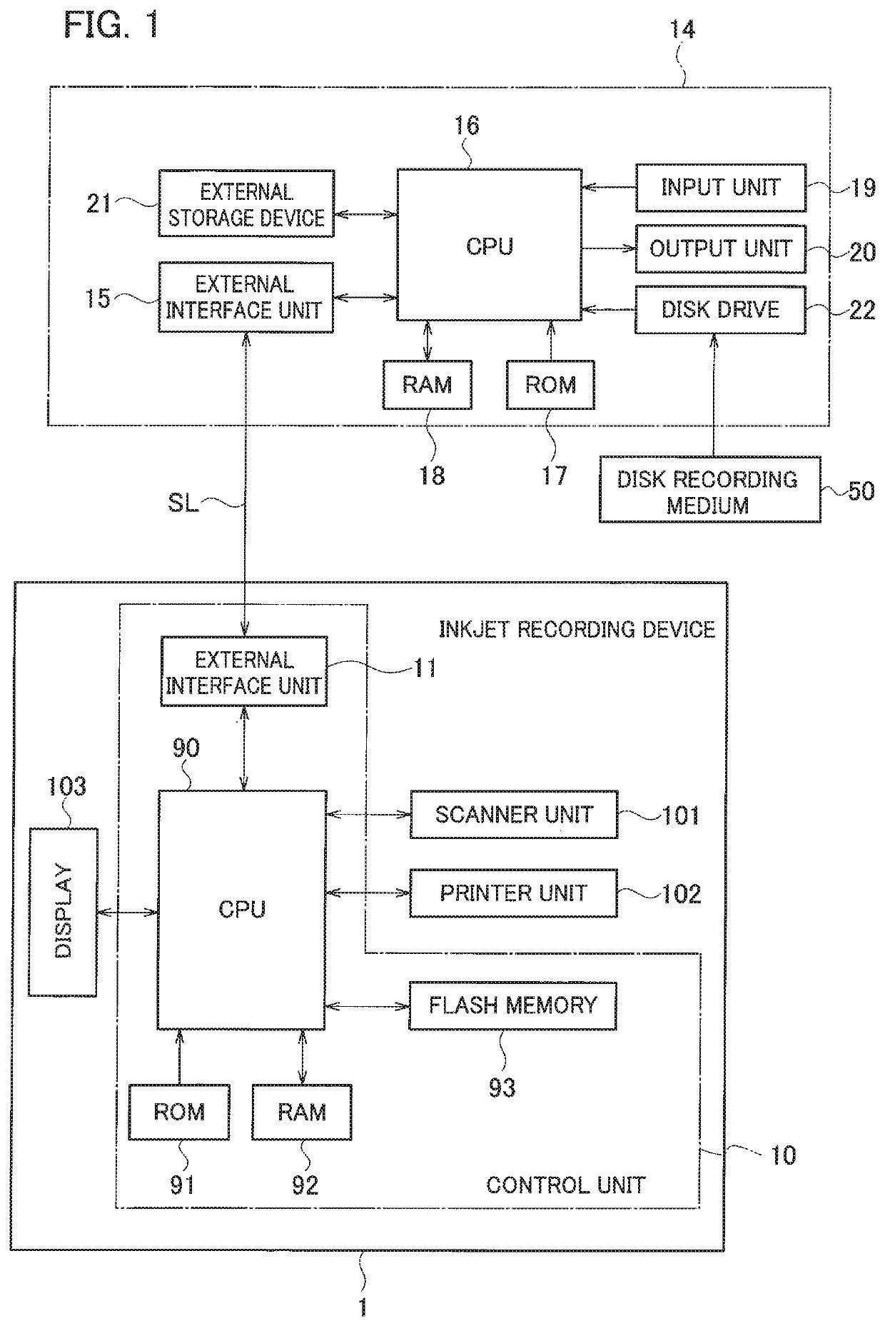
[0032]FIG. 1 is a block diagram illustrating a configuration of a control system of a line-type inkjet recording device according to an embodiment of the present invention.

[0033]As illustrated in FIG. 1, a line-type inkjet recording device (hereinafter, abbreviated as “inkjet recording device”) 1 according to the present embodiment includes a scanner unit 101 that outputs an image signal by reading an original document image on an original document, a printer unit 102 that prints (records) the original document image on printing paper (single side or double sides) based the image signal output from the scanner unit 101, ...


PUM


Abstract

Density of each pixel is specified from a test pattern for measurement of density distribution, a density profile indicating distribution of the specified density for each pixel is acquired, and a pixel region including a “nozzle of interest” having a certain density difference or more from surrounding pixels and pixels on both sides thereof is extracted as a nozzle region of interest from the acquired density profile. Filters B to E, other than a filter A to be applied for density smoothing processing of pixels that do not belong to the nozzle region of interest, are applied for the density smoothing processing of the pixels in the nozzle region of interest, to generate a profile of a density correction value for eliminating a density difference between respective pixels based on the density profile after the smoothing processing.

Description

TECHNICAL FIELD[0001]The present invention relates to a density correction profile generation method and an image forming device.BACKGROUND ART[0002]As one of image forming devices, there is an inkjet recording device that forms an image by discharging ink from a plurality of nozzles of an inkjet head to a recording medium conveyed on a conveyance path. In the inkjet recording device, if there are variations in ink discharge characteristics among the respective nozzles, density unevenness is generated in an image due to the size or displacement of positions of dots formed on a recording medium such as printing paper.[0003]Therefore, it has been known to measure the ink discharge characteristics for each nozzle and calculate a density correction value for canceling the variations in the ink discharge characteristics among the nozzles, to correct a density gradation value of a pixel corresponding to each nozzle by using the calculated correction value.[0004]The density correction valu...

Claims


Application Information

Patent Timeline
Patent Type & Authority Patents(United States)
IPC IPC(8): B41J2/21B41J2/20B41J2/12B41J2/205
CPCB41J2/2054B41J2/2139B41J2/12G06K15/027B41J29/02B41J29/38B41J2/04508B41J2/04581
Inventor INAGAWA, HIRONORI
Owner RISO KAGAKU CORP
Why Eureka
Try Eureka