Detector and roller arrangement for an image forming apparatus

a technology of image forming apparatus and detector, which is applied in the direction of electrographic process apparatus, instruments, optics, etc., can solve the problems of detection errors, adversely affecting detection precision, and unexpected detection outputs, so as to prevent uneven density, reduce image density, and improve accuracy

Active Publication Date: 2013-05-21
RICOH KK
View PDF23 Cites 3 Cited by
  • Summary
  • Abstract
  • Description
  • Claims
  • Application Information

AI Technical Summary

Benefits of technology

[0011]Accordingly, the present invention provides a novel image forming apparatus capable of controlling the image density with higher precision and preventing uneven density and decrease in the image density from occurring over time.

Problems solved by technology

When detecting the toner density, the condition of the detection target surface may adversely affect the detection precision.
For example, projections and scratches on the surface to be detected of the intermediate transfer body may cause detection errors.
In such a case, foreign particles on the inner surface of the belt or projections on the outer surface of the belt may result in unexpected detection outputs.
However, this disclosed art cannot improve the detection precision because the roller is formed of a metal and the belt slips along it too easily.

Method used


Image

  • Detector and roller arrangement for an image forming apparatus
  • Detector and roller arrangement for an image forming apparatus
  • Detector and roller arrangement for an image forming apparatus

Examples


modified example

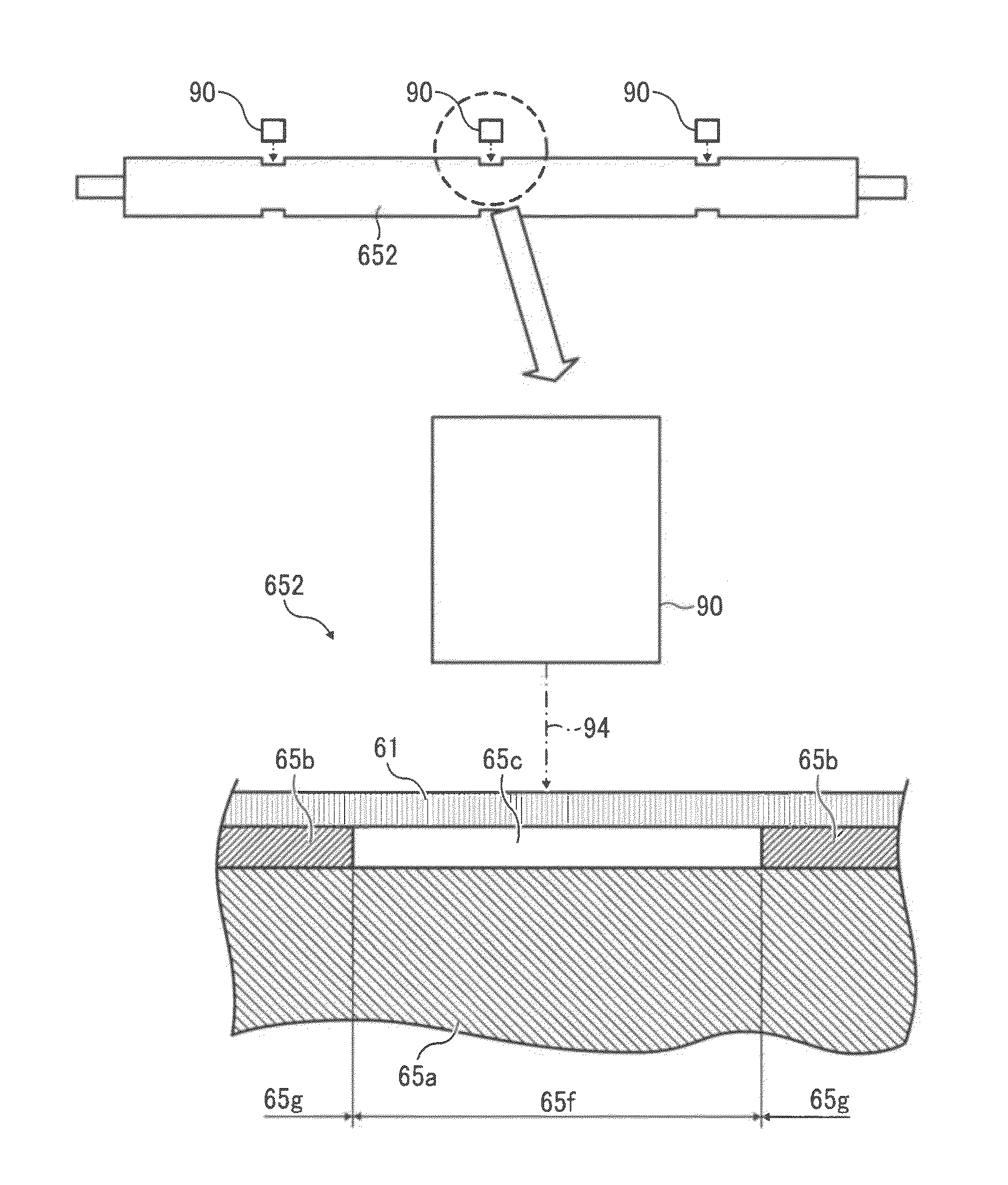
[0153]As illustrated in FIG. 15, a rubber layer 65b formed on the metal core 65a having a same diameter is formed to have a different thickness in the belt width direction. Alternatively, a metal core 65a with a different diameter in the belt width direction is first formed and a thin rubber layer 65b is formed on the metal core 65a to form a drive roller 652.

[0154]If there is a layout-derived restriction from the transfer unit 60 having an intermediate transfer belt 61, any roller 65 other than the drive roller 652 is formed with a groove and a detection sensor 90 may be provided either upstream or downstream of the roller 65 on which the groove is formed.

[0155]A gap 65c may be formed not only to a single roller 65 but to a plurality of rollers 65 or all rollers 65 which contact the intermediate transfer belt 61. The gap 65c may be provided to all rollers other than the repulsive force roller 654 disposed opposite in the secondary transfer position.

[0156]Part of the rubber layer 65...


PUM


Abstract

An image forming apparatus includes an endless intermediate transfer belt rotatably stretched over a plurality of rollers, and a detector to read a pattern on the intermediate transfer belt. One of the rollers includes a first portion disposed opposite an area on the intermediate transfer belt including a pattern passing position, and a second portion not including a pattern passing position. The first portion has a diameter smaller than that of the second portion thereof, and an elastic material is superimposed on the second portion only. The detector is disposed between a second roller disposed upstream of the first roller and a third roller disposed downstream of the first roller, and opposite the intermediate transfer belt.

Description

CROSS-REFERENCE TO RELATED APPLICATIONS[0001]The present application claims priority from Japanese patent application number 2010-038320, filed on Feb. 24, 2010, the entire contents of which are incorporated by reference herein.BACKGROUND OF THE INVENTION[0002]1. Field of the Invention[0003]The present invention relates to an image forming apparatus such as a copier, printer, facsimile machine, or the like, and in particular relates to an image forming apparatus using an intermediate transfer device.[0004]2. Description of the Related Art[0005]In image forming apparatuses such as copiers, printers, or facsimile machines, a transfer process is performed in which a toner image obtained by developing an electrostatic latent image formed on a photoreceptor (being a latent image carrier) is transferred to a recording medium such as a sheet.[0006]In such a transfer process, there is a case of transferring a monochromatic image in which the toner image is directly transferred from the phot...

Claims


Application Information

Patent Timeline
Patent Type & Authority Patents(United States)
IPC IPC(8): G03G15/00G03G15/01
CPCG03G15/50G03G2215/0129G03G2215/0161G03G15/0136G03G15/1615
Inventor FUJITA, JUNPEIMIMBU, RYUUICHISENGOKU, KENJIICHIHASHI, OSAMU
Owner RICOH KK
Why Eureka
Try Eureka