Image forming apparatus and density unevenness preventing method

a technology of density unevenness and forming apparatus, which is applied in the direction of printing and other printing apparatus, can solve the problems of increasing parts cost, uneven recording material speed, density unevenness in the image, etc., and achieves the effect of increasing parts cost and preventing density unevenness

Inactive Publication Date: 2007-03-13
FUJIFILM HLDG CORP +1
View PDF5 Cites 3 Cited by
  • Summary
  • Abstract
  • Description
  • Claims
  • Application Information

AI Technical Summary

Benefits of technology

[0008]An object of the present invention is to provide an image forming apparatus in which density unevenness can be surely prevented without increasing parts cost, and a method for preventing the density unevenness.
[0010]A test pattern recorded on the test print is measured by a density measuring sensor. A density profile with respect to the feeding direction of the recording material is created based on the density measurement. The density unevenness to change periodically is extracted from the density profile to obtain a relationship between a motor rotating position and the amount of density variation (density unevenness component) of the density unevenness in one period. The density unevenness in one period is a distance from a first position showing first reference density in the test print to a second position showing the subsequent reference density. The feeding distance of the recording material from the print start to the first position is stored. The motor speed is controlled in reference to the speed control profile on each distance of one period from the first position. The speed control profile lengthens a period of a driving pulse at the motor rotating position where the density is low, while shortens the period at the motor rotating position where the density is high.
[0013]According to the image forming apparatus and the density unevenness preventing method of the present invention, the motor speed is controlled based on the speed control profile (period profile) in recording the image, so that the density unevenness can be surely prevented without increasing the parts cost.

Problems solved by technology

In the above-mentioned image forming apparatus, the feeding speed of the recording material may be uneven mainly due to an eccentric or distorted rotation shaft of the motor, and this may cause density unevenness in the image along the feeding direction of the recording material.
In the prior art image forming apparatus, although the parts accuracy of the feed driving system is enhanced in order to eliminate the density unevenness due to the unevenness in the feeding speed, there arises a problem that the parts cost is increased.
In addition, the above-mentioned image forming apparatuses deter the occurrence of the density unevenness by controlling the driving timing of the recording head and the optical writer; however, since the output from the recording head and the optical writer are greatly influenced by incidental parameters such as environmental temperature and humidity around the image forming apparatus, it is difficult to prevent the density unevenness surely.

Method used


Image

  • Image forming apparatus and density unevenness preventing method
  • Image forming apparatus and density unevenness preventing method
  • Image forming apparatus and density unevenness preventing method

Examples


Embodiment Construction

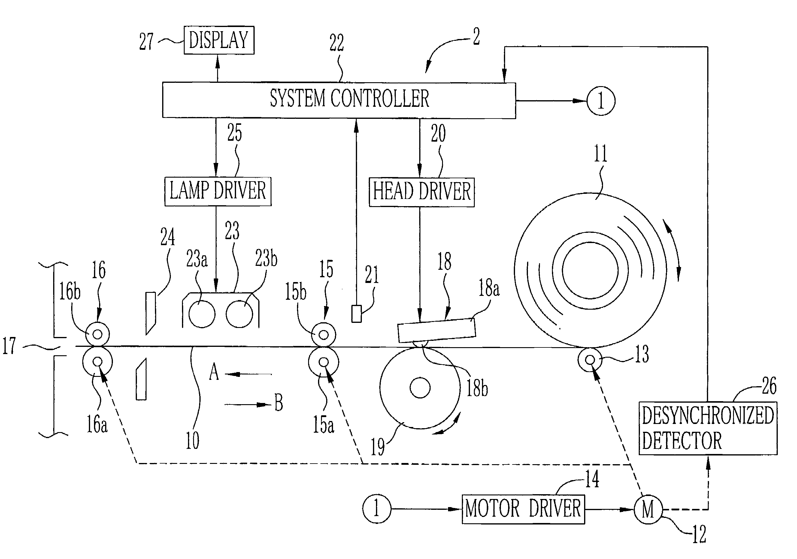
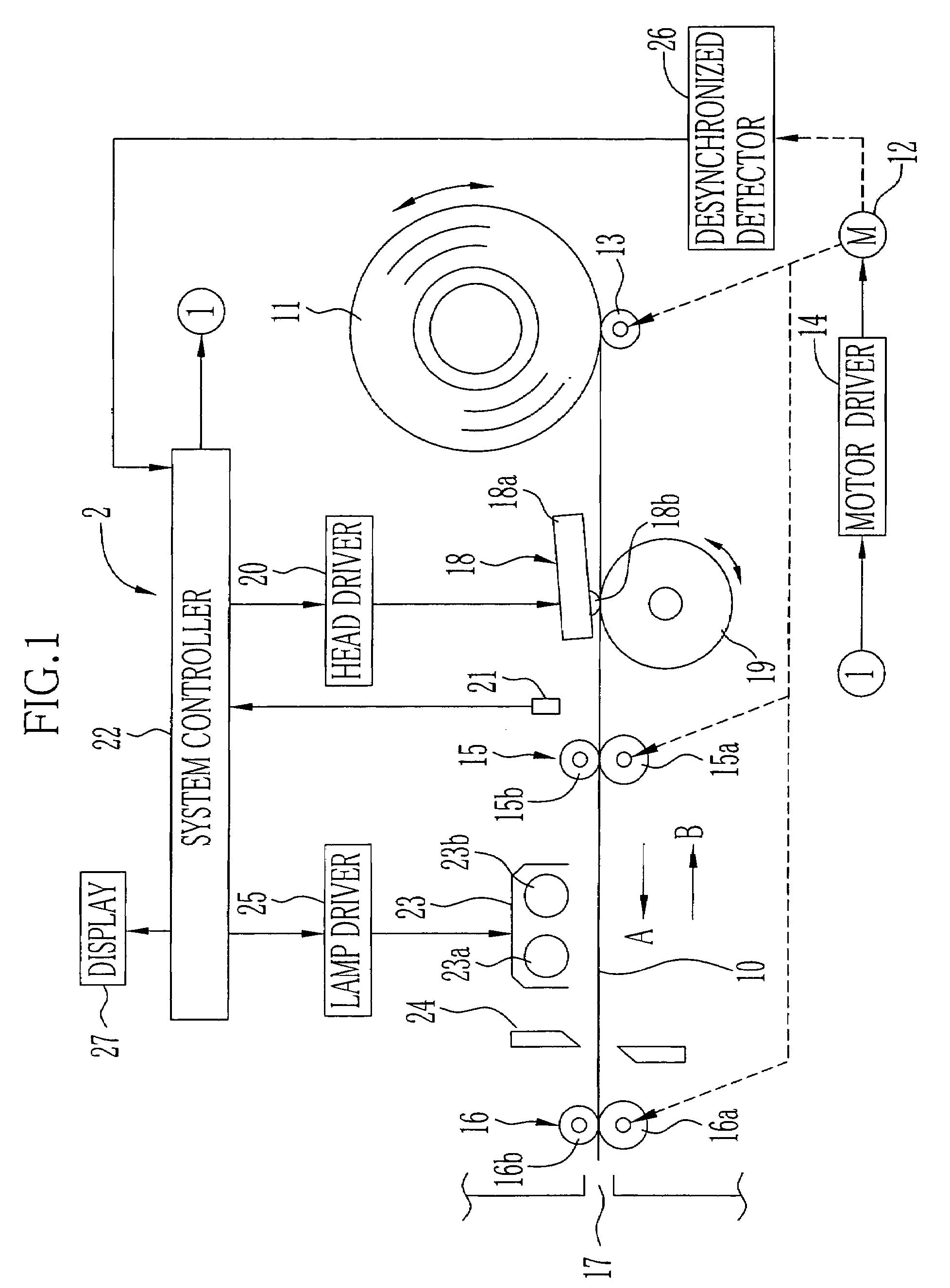
[0021]In FIG. 1, a continuous color thermal recording paper 10 is used as a recording material in a color thermal printer 2. The color thermal recording paper 10, which is wound into a roll shape, is loaded into the color thermal printer 2 as a recording paper roll 11.

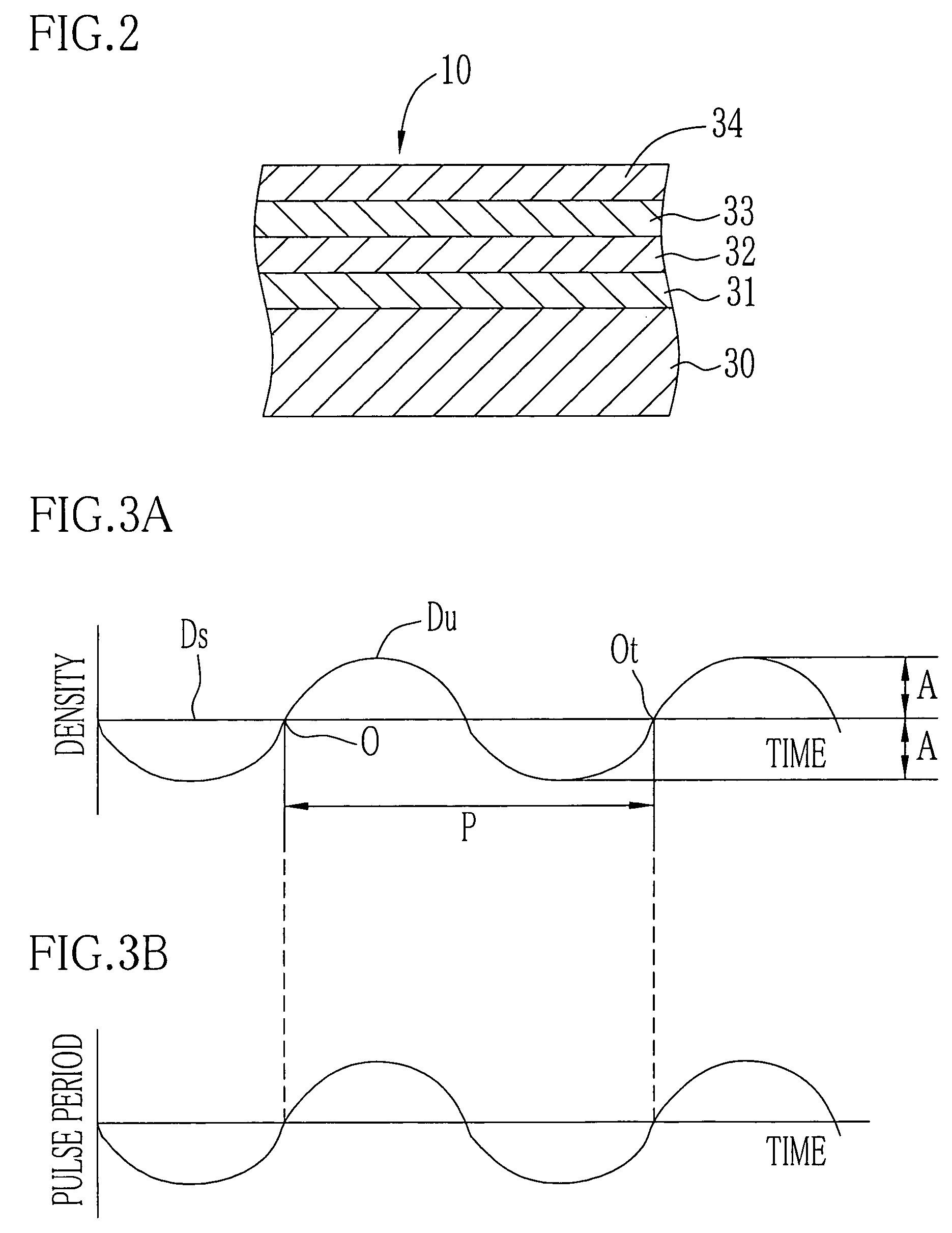
[0022]As shown in FIG. 2, the color thermal recording paper 10 includes a cyan thermosensitive coloring layer 31, a magenta thermosensitive coloring layer 32, a yellow thermosensitive coloring layer 33, and a protective layer 34 overlaid on a support 30 in sequence. The yellow thermosensitive coloring layer 33, which is the uppermost layer, has the highest heat sensitivity and develops the yellow color by application of relatively low heat energy. The cyan thermosensitive coloring layer 31, which is the lowermost layer, has the lowest heat sensitivity and develops the cyan color by application of relatively high heat energy.

[0023]The yellow thermosensitive coloring layer 33 loses its coloring ability when near-ultravio...


PUM


Abstract

A system controller of a color thermal printer obtains a density profile of an image with respect to a feeding direction of a color thermal recording paper based on density of a test print measured by a CCD line sensor, and then extracts a density unevenness component, which fluctuates periodically, from the density profile. The system controller relates the density unevenness component in one period to a rotating position of a feed motor so as to create a period profile of a driving pulse to offset the unevenness component. When recording the image, the driving pulse is given to the feed motor based on the period profile, so that the drive of the feed motor is controlled.

Description

BACKGROUND OF THE INVENTION[0001]1. Field of the Invention[0002]The present invention relates to a method for preventing density unevenness in an image with respect to a feeding direction of a recording material, and an image forming apparatus having a function for preventing density unevenness.[0003]2. Description of the Prior Arts[0004]As an image forming apparatus for recording an image on a recording material, there are an inkjet printer with an inkjet head and a thermal printer with a thermal head. In these printers, the recording material is fed by a feed roller pairs to be driven by a motor.[0005]In the above-mentioned image forming apparatus, the feeding speed of the recording material may be uneven mainly due to an eccentric or distorted rotation shaft of the motor, and this may cause density unevenness in the image along the feeding direction of the recording material. The density unevenness occurs periodically. Therefore, the parts for the feed transport driving system, f...

Claims


Application Information

Patent Timeline
Patent Type & Authority Patents(United States)
IPC IPC(8): B41J2/00B41J11/42B41J2/32B41J2/325B41J2/36B41J29/46
CPCB41J2/36
Inventor IMAI, RYO
Owner FUJIFILM HLDG CORP
Why Eureka
Try Eureka