Polarization switching liquid crystal element and image display apparatus having the same

a liquid crystal element and polarization switching technology, applied in static indicating devices, instruments, non-linear optics, etc., can solve the problems of unstable durability of ferroelectric liquid crystal, high cost, and inability to use, and achieve the effect of reducing wavelength dependence, high response speed and high durability

Inactive Publication Date: 2011-07-19
OLYMPUS CORP
View PDF10 Cites 1 Cited by
  • Summary
  • Abstract
  • Description
  • Claims
  • Application Information

AI Technical Summary

Benefits of technology

[0015]The first purpose of the present invention in view of the above circumstances is to provide a polarization switching liquid crystal element having a high response speed and reduced wavelength-dependency using inexpensive and highly durable TN liquid crystal without increasing parts cost.
[0016]The second purpose of the present invention is to provide an image display apparatus in which the above polarization switching liquid crystal element is used for pixel-shifting so as to prevent false colors and provide high-quality and resolution images.
[0045]and the phase difference u includes a value 1.7 and the transmittance T is 0.1 or lower when the λ ranges from 400 nm to 700 nm; therefore, a high response speed and reduced wavelength-dependency are realized using inexpensive and highly durable TN liquid crystal without increasing parts cost.
[0046]Furthermore, using the above polarization switching liquid crystal element for pixel shifting, the image display apparatus of the present invention provides high quality and high resolution images while preventing false colors.

Problems solved by technology

However, ferroelectric liquid crystal is unstable in terms of durability and expensive and therefore not practical.
However, TN liquid crystal generally has a lower response speed compared with ferroelectric liquid crystal.
However, when the cell gap is simply reduced, the rotation of the polarization becomes wavelength-dependent.
In such a case, the addition of phase plates increases parts cost.
However, ferroelectric liquid crystal is unstable in terms of durability and expensive as described above and is therefore not practical.
However, this technique has limitations in applying to field-sequential image display apparatuses in which R, G, and B colors are sequentially displayed.
For example, when the cell gap is reduced in order to increase the response speed of TN liquid crystal, false colors appear because of the wavelength-dependent light rotation property, deteriorating the displayed image quality.
However, parts cost may be increased as described above.

Method used


Image

  • Polarization switching liquid crystal element and image display apparatus having the same
  • Polarization switching liquid crystal element and image display apparatus having the same
  • Polarization switching liquid crystal element and image display apparatus having the same

Examples


embodiment 1

[0153]FIG. 10 is a schematic illustration showing the structure of Embodiment 1 of the image display apparatus of the present invention.

[0154]This image display apparatus is a projector realizing two-pixel shifting (wobbling) in the horizontal direction using the above described polarization switching liquid crystal element 1 of the present invention, comprising a color field-sequential illumination means 21 capable of color field-sequential illumination, a spatial light modulation element 22 for displaying input image signals, an illumination optical system 23 efficiently guiding illumination light from the color field-sequential illumination means 21 to the spatial light modulation element, a pixel shifting optical unit 24 including the polarization switching liquid crystal element 1, a projection optical system 26 for enlarging and projecting light having passed through the pixel shifting optical unit 24 on a screen 25, a modulation element drive circuit 27 driving the spatial li...

embodiment 3

[0187]FIG. 16 is a schematic illustration showing the structure of Embodiment 3 of the image display apparatus of the present invention. The image display apparatus of this embodiment has the simultaneous display spatial light modulation element 22 consisting of a reflective LCD. Therefore, a PBS 41 is placed between the illumination optical system 23 and the spatial light modulation element 22. Illumination light incident on the spatial light modulation element 22 and reflected light modulated by the spatial light modulation element 22 are polarized and separated by the PBS41. The modulated light separated by the PBS 41 reaches the pixel shifting units 24a and 24b.

[0188]This embodiment uses the spatial light modulation element 22 of a reflective type. Therefore, the optical path between the spatial light modulation element 22 and the polarization switching liquid crystal element 1a constituting the optical unit 24a is extended. However, the spatial light modulation element 22 is o...

embodiment 2

[0192]The R, G, and B lights modulated by the spatial light modulation elements 22R, 22G, and 22B, respectively, are combined by a color combining prism 59. The combined R, G, and B lights are subject to four-pixel shifting in the horizontal and vertical directions through the two sets of pixel shifting optical units 24a and 24b and projected on the screen 25 by the projection optical system 26 as in

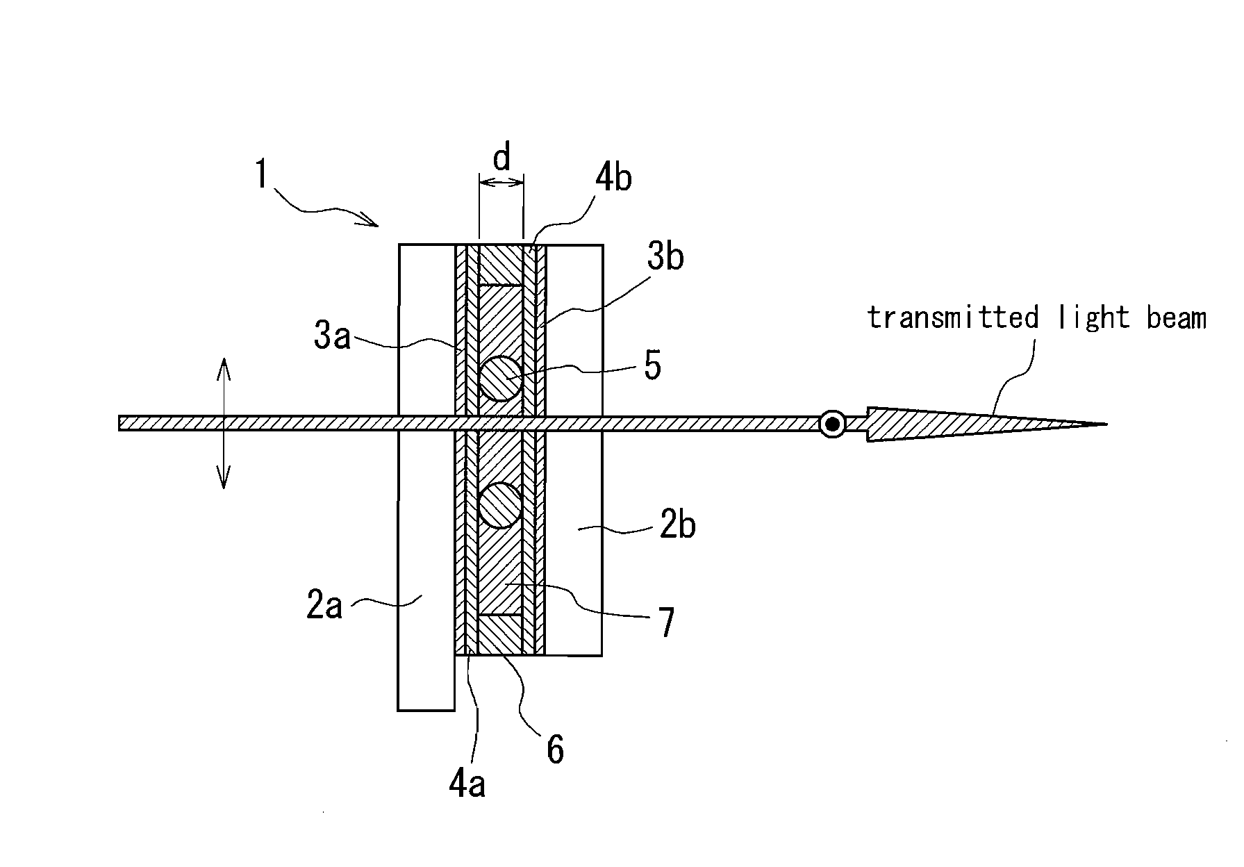
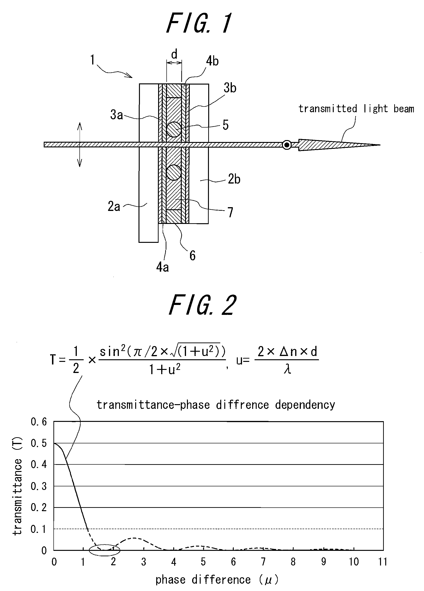
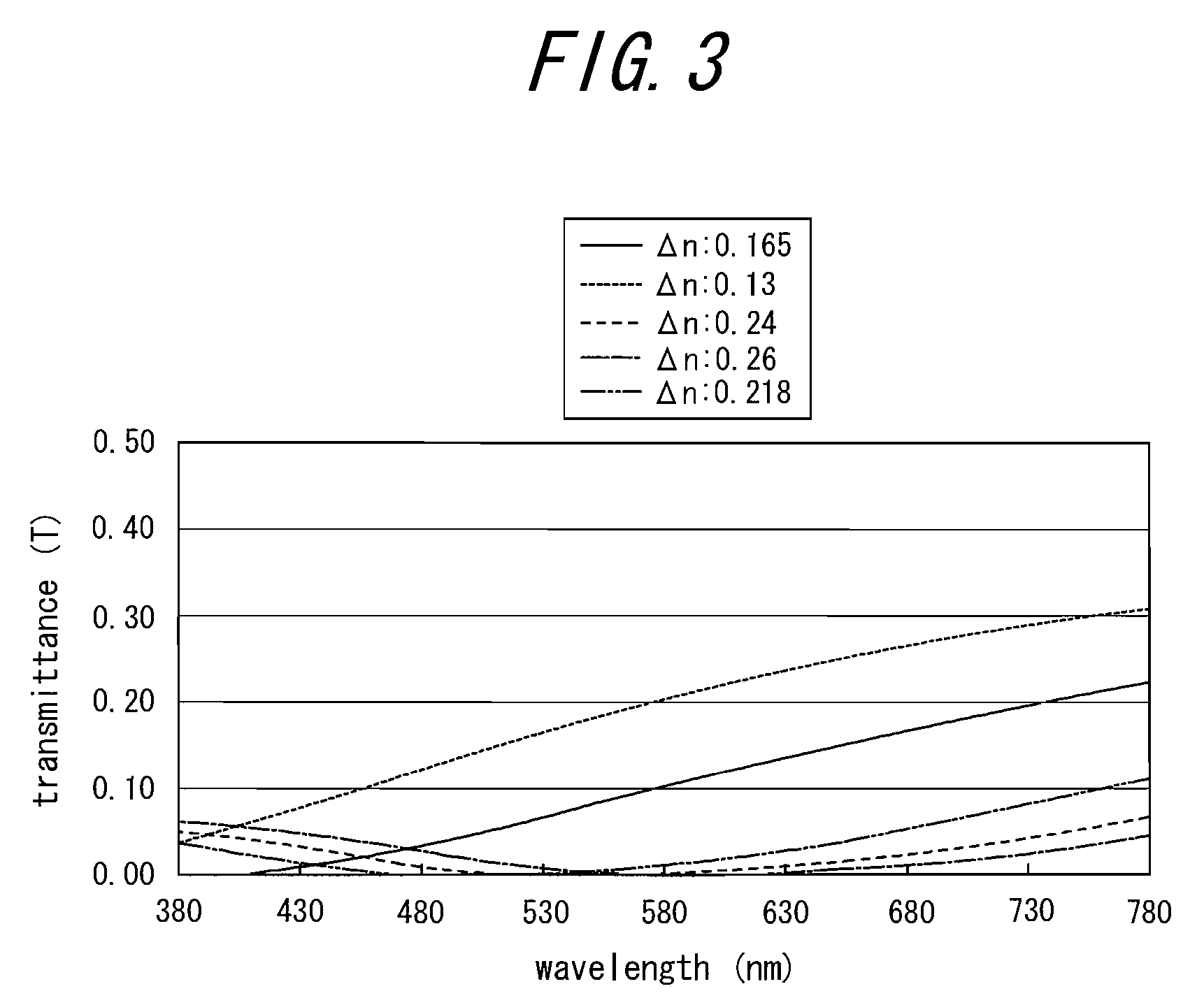
[0193]Here, when the polarization switching liquid crystal element constituting a pixel shifting optical unit has a wavelength-dependent polarization ratio as in the prior art, this three-plate system is subject to different degrees of crosstalk and consequently false colors for different colors. However, in this embodiment, the polarization switching liquid crystal elements 1a and 1b of the present invention described with reference to FIGS. 1 to 9 constitute the pixel shifting optical units 24a and 24b. Therefore, a high resolution three-plate image display apparatus with reduced false...


PUM

PropertyMeasurementUnit
thicknessaaaaaaaaaa
inclination angleaaaaaaaaaa
visible light wavelengthsaaaaaaaaaa

Abstract

The present invention provides a polarization switching liquid crystal element 1 having TN liquid crystal 7 retained between two transparent substrates 2a and 2b for transmitting at least visible polarized light with the polarized light transmission axis selectively rotated by 90 degrees when a voltage is selectively applied to the TN liquid crystal 7, wherein a phase difference u of said TN liquid crystal 7 is defined by the following equation: u=2×Δn×d / λ, where Δn is the refractive index anisotropy of said TN liquid crystal 7, d is the thickness of said TN liquid crystal 7, and λ is the wavelength of said polarized light, and a transmittance T of said polarization switching liquid crystal element measured with polarization plates on the incident and outgoing sides is defined by the following equation: T=(½)×sin2{π(1+u2)1 / 2 / 2} / (1+u2), and wherein the phase difference u includes a value 1.7 and the transmittance T is 0.1 or lower when the λ ranges from 400 nm to 700 nm. Then, a polarization switching liquid crystal element having a high response speed and reduced wavelength-dependency can be realized using inexpensive and highly durable TN liquid crystal without increasing parts cost.

Description

CROSS-REFERENCE TO RELATED APPLICATION[0001]The present application is a Continuing Application based on International Application PCT / JP2006 / 316426 filed on Aug. 22, 2006, which, in turn, claims the priority from Japanese Patent Application No. 2005-316864 filed on Oct. 31, 2005, the entire disclosure of these earlier applications being herein incorporated by reference.TECHNICAL FIELD[0002]The present invention relates to a polarization switching liquid crystal element and an image display apparatus, such as a projector, having the same.BACKGROUND OF THE INVENTION[0003]Many liquid crystal elements are used in display applications. Many liquid crystal elements in display applications realize a gradation display, not a two-grade, black and white display. In addition, various techniques have been developed in pursuing improved viewing angles required for viewing from different angles.[0004]On the other hand, liquid crystal elements in applications other than display include a liquid c...

Claims


Application Information

Patent Timeline
Patent Type & Authority Patents(United States)
IPC IPC(8): G02F1/1335G02F1/13
CPCG02F1/1396G09G3/003H04N9/3114H04N9/3167H04N9/3197G03B21/2073G09G3/001G09G2320/0242G03B21/006G03B33/08G03B33/12
Inventor YAMANAKA, KAZUYA
Owner OLYMPUS CORP
Why Eureka
Try Eureka