Method and device for feeding and attaching corrective elements for unbalance correction, in particular in a balancing machine

a technology of unbalance correction and corrective elements, which is applied in the direction of static/dynamic balance measurement, manufacturing tools, instruments, etc., can solve the problems of complex and expensive manufacture of known devices, inability to move shuttles, and relatively heavy carriages, etc., and achieves speed and reliability. high, the effect of simple structur

Active Publication Date: 2011-09-22
SCHENCK ROTEC GMBH
View PDF9 Cites 10 Cited by
  • Summary
  • Abstract
  • Description
  • Claims
  • Application Information

AI Technical Summary

Benefits of technology

[0008]It is an object of the present invention to provide a device of the type initially referred to and a method which enable the corrective elements to be fed from the supply unit to the attachment device with particular ease, speed and reliability.

Problems solved by technology

The known device is complicated and expensive to manufacture because of the need to provide pneumatic devices on the shuttle and the welding device which have to be controllably activated for transferring and holding the metal element.
Another disadvantage is that the shuttle cannot be moved into the working area of the welding device so that it is necessary for the welding device to leave its working area to pick up the metal element for welding.
As a result, the carriage is relatively heavy and requires complex feeding devices so that the traversing speed has to be kept at a low level.

Method used


Image

  • Method and device for feeding and attaching corrective elements for unbalance correction, in particular in a balancing machine
  • Method and device for feeding and attaching corrective elements for unbalance correction, in particular in a balancing machine
  • Method and device for feeding and attaching corrective elements for unbalance correction, in particular in a balancing machine

Examples


Embodiment Construction

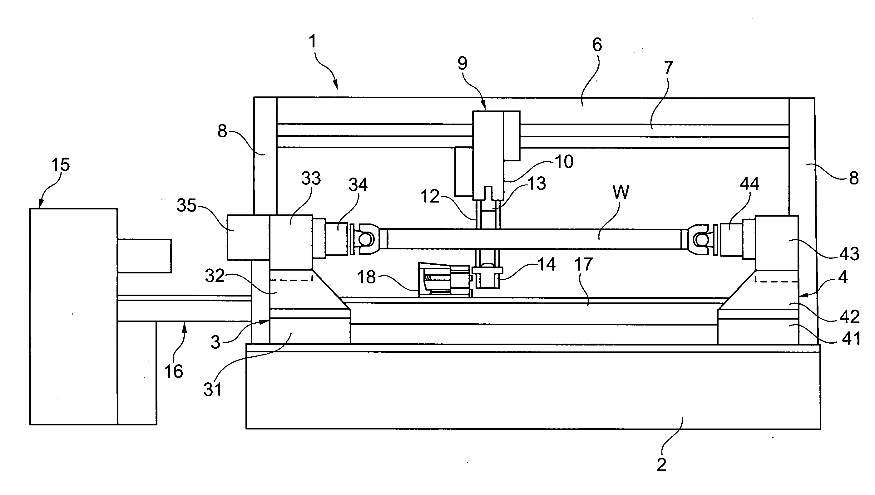
[0033]FIG. 1 shows a balancing machine 1 for balancing propeller shafts. The balancing machine includes a machine bed 2 on which two pedestals 3, 4 are arranged at opposite ends. Each of the pedestals 3, 4 has a base 31, 41 which is carried in a straight-line guide extending in the longitudinal direction of the machine bed 2 and is movable relative to the machine bed 2 by means of a traversing drive in order to enable the relative distance of the pedestals 3, 4 to be adjusted to the length of the propeller shaft to be balanced. Extending upwardly from the bases 31, 41 are, respectively, leaf springs 32, 42 arranged in pairs. Secured to the upper ends of each pair of leaf springs 32, 42 is a respective spindle housing 33, 43 each receiving a spindle mounted therein for rotation. The spindles of the spindle housings 33, 43 are coaxially arranged and have at their ends facing each other a respective clamping fixture 34, 44 for clamping a fastening end, for example, the end flange of a ...


PUM

PropertyMeasurementUnit
circumferenceaaaaaaaaaa
range of movementaaaaaaaaaa
forceaaaaaaaaaa

Abstract

Disclosed is a device for feeding and attaching corrective elements for unbalance correction on propeller shafts in a balancing machine, which includes an attachment device adapted to be positioned longitudinally to the rotor axis, with a receptacle for receiving a corrective element attachable to the outer circumference of the rotor. Associated with the balancing machine is a supply unit supplying corrective elements measured for the individual unbalance correction. A feeding device is provided which feeds supplied corrective elements to the attachment device, said feeding device including a transfer shuttle capable of performing reciprocating movements between the supply unit and the attachment device on a guideway parallel to the rotor axis by means of a controllable motion drive mechanism. The transfer shuttle includes a loading device configured for performing an active loading operation by displacing a corrective element from a receptacle of the transfer shuttle into the receptacle of the attachment device, said loading device being driven by means of the controllable motion drive mechanism of the transfer shuttle.

Description

CROSS REFERENCE TO RELATED APPLICATIONS[0001]Applicants claim priority under 35 U.S.C. §119 of German Patent Application No. 10 2010 003 085.6 filed Mar. 19, 2010.FIELD OF THE INVENTION[0002]This invention relates to a device for feeding and attaching corrective elements for unbalance correction to rotors having a rotor axis, in particular to propeller shafts, preferably in a balancing machine, with at least one attachment device adapted to be positioned longitudinally to the rotor axis and suitable for attaching a corrective element to the outer circumference of the rotor, with a stationary supply unit supplying corrective elements measured for the individual unbalance correction, and with a feeding device adapted to feed supplied corrective elements to the attachment device, said feeding device including a transfer shuttle having a receptacle for receiving a corrective element and being capable of performing reciprocating movements between the supply unit and the attachment device...

Claims


Application Information

Patent Timeline
Patent Type & Authority Applications(United States)
IPC IPC(8): G01M1/16
CPCY10T29/53061G01M1/32G01M1/02
Inventor ROGALLA, MARTINEBERT, KUNOMUTH, CHRISTIAN
Owner SCHENCK ROTEC GMBH
Why Eureka
Try Eureka