
Electronic camera and image processing program

Inactive Publication Date: 2006-01-24
NIKON CORP
View PDF23 Cites 10 Cited by
  • Summary
  • Abstract
  • Description
  • Claims
  • Application Information

AI Technical Summary

Benefits of technology

[0013]An object of the present invention is to provide an electronic camera capable of reliably minimizing the occurrence of block noise, sustaining a correct compression distribution of the DC component / AC component and executing the compression size adjustment with ease and reliability.
[0014]Another object of the present invention is to provide an image processing program for implementing image compression processing that makes it possible to reliably minimize the occurrence of block noise, maintain a correct compression distribution of the DC component / AC component and execute compression size adjustment with ease and reliability.
[0016]Since the DC / AC quantization ratio is determined in correspondence to the target compression rate, the DC / AC quantization ratio can be set so as to ensure that no block noise will manifest in a situation in which block noise would occur if the constant DC / AC quantization ratio remained unchanged at all times, for instance. In addition, since the DC component quantization step and the AC component quantization step are adjusted while sustaining the DC / AC quantization ratio at a substantially constant value, the processing is simplified compared to processing achieved by individually adjusting the DC component quantization step and the AC component quantization step and furthermore, the compression code volume can be adjusted while maintaining good balance in the compression distribution of the DC component and the AC component.
[0018]Moreover, the quantization ratio determining processing unit may fix the DC / AC quantization ratio at a constant value regardless of the target compression rate setting when the target compression rate is higher than a predetermined value.

Problems solved by technology

When the scale factor SF increases, the step taken to quantize the DC component becomes larger and, as a result, significant quantization noise manifests in the quantized DC component.
Such quantization noise in the DC component then manifests as pronounced block noise in the decompressed image.
However, these measures frequently lead to an undesirable phenomenon on the opposite extreme in that if the scale factor SF is set to a relatively small value to process image data with a small information volume, the AC component quantization step becomes smaller than the DC component quantization step.
When such a reverse phenomenon occurs, the compression distribution of the DC component / AC component becomes poor and the priority of compression is not given to information which is visually important.
In addition, the effects of the individual parameters on the compression size and the compressed image quality are complex and indeterminate.
For this reason, it is difficult to execute the correct compression processing by individually adjusting these parameters during the compression size adjustment.
Furthermore, there is another problem in that since the number of options for each parameter increases, the compression size adjustment cannot be completed quickly.

Method used


Image

  • Electronic camera and image processing program
  • Electronic camera and image processing program
  • Electronic camera and image processing program

Examples


Embodiment Construction

[0028]An embodiment of the present invention is now explained in reference to the drawings.

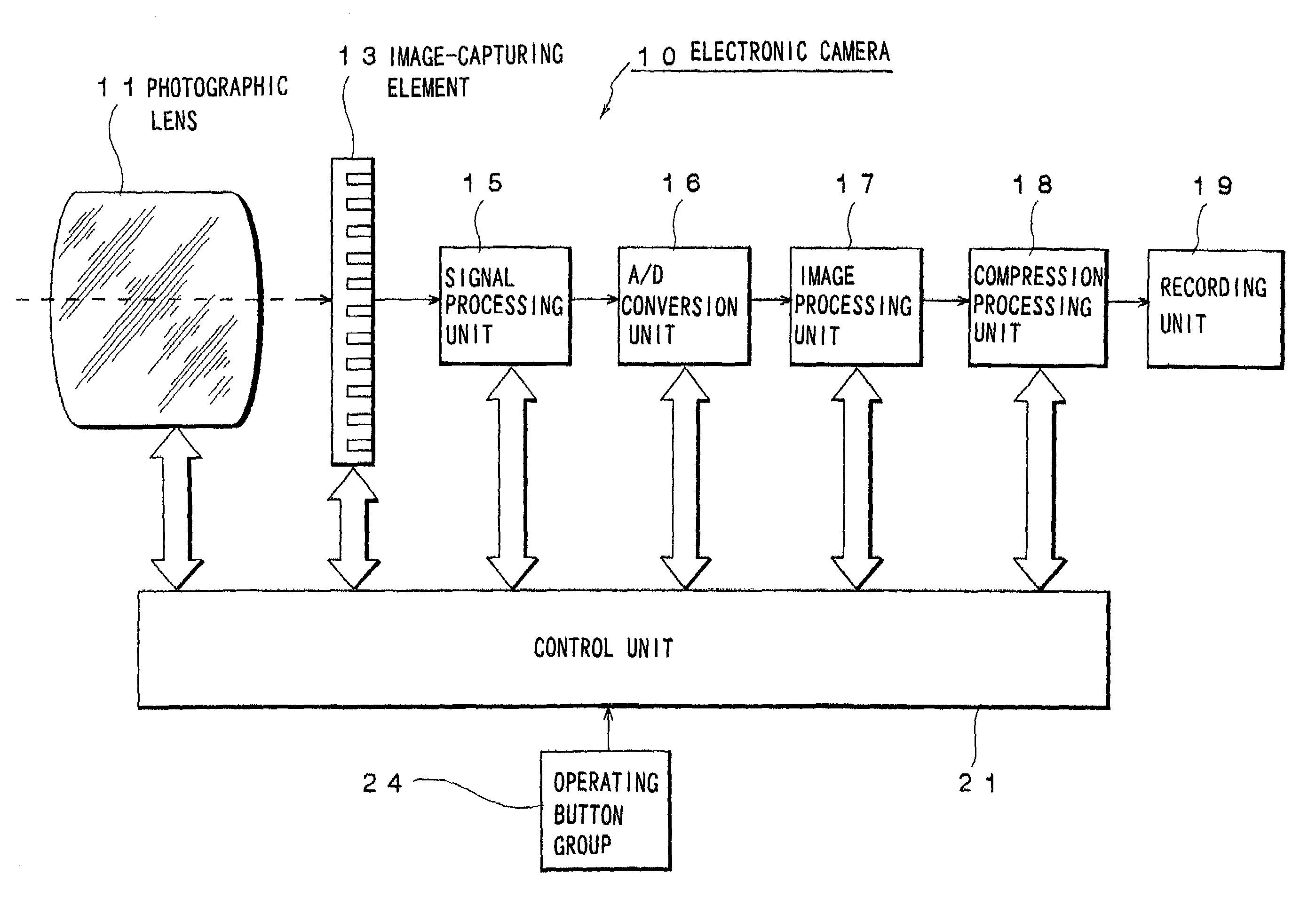
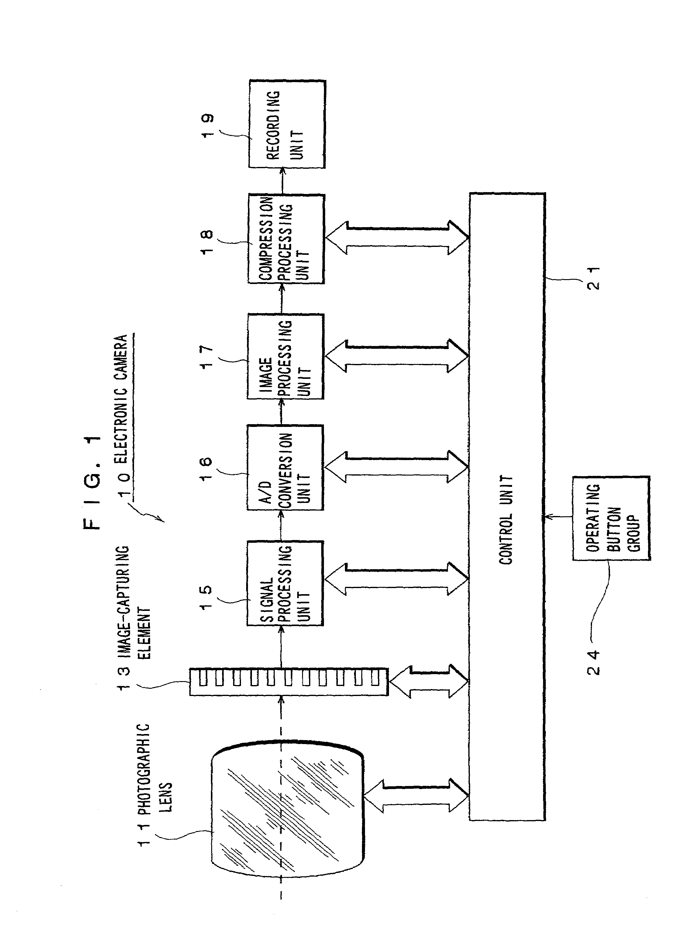
[0029]FIG. 1 is a schematic block diagram illustrating the structure of an electronic camera 10. The electronic camera 10 in FIG. 1 is mounted with a photographic lens 11. An image-capturing element 13 is provided in the image space of the photographic lens 11. Image data generated at the image-capturing element 13 sequentially undergo specific types of processing at a signal processing unit 15, an A / D conversion unit 16 and an image processing unit 17, and then are input to a compression processing unit 18 as digital image data. The compression processing unit 18 performs JPEG compression on the input image data and outputs compressed data to a recording unit 19. The recording unit 19 records the input compressed image data to a recording medium (not shown) which may be a memory card.

[0030]In addition, the electronic camera 10 is provided with a control unit 21 for implementing system control...


PUM


Abstract

As the target compression rate is set higher, the ratio of a DC component quantization step and an AC component quantization step (referred to as a “DC / AC quantization ratio” is adjusted to a smaller value and then a compression size adjustment is implemented while sustaining the DC / AC quantization ratio at a substantially constant value. In addition, if the compression rate is set higher than a predetermined factor, the DC / AC quantization ratio is fixed at a constant value regardless of the target compression rate setting to prevent the DC component quantization step from becoming excessively small.

Description

[0001]The disclosures of the following priority application is herein incorporated by reference:[0002]Japanese Patent Application No. H 11-230593 filed Aug. 17, 1999TECHNICAL FIELD[0003]The present invention relates to an electronic camera and an image processing program having an image compression function.BACKGROUND ART[0004]Image data handled in an electronic camera or a computer normally undergo image compression (e.g., JPEG compression) processing, in order to efficiently record the image data at a recording medium. The image compression processing may be executed through, for instance, the following steps 1˜6.1. The electronic camera determines a target image data compression rate in correspondence to the compressed image quality setting selected by the photographer (e.g., by switching to one of; FINE / NORMAL / BASIC).[0005]2. The electronic camera divides the image data constituted of the brightness Y and the color differences Cb, Cr blocks each made up of, for instance, 8×8 pix...

Claims


Application Information

Patent Timeline
IPC IPC(8): G06K9/36H04N5/225H04N1/41H04N19/124H04N19/134H04N19/60H04N19/86
CPCH04N1/41H04N19/176H04N19/172H04N19/15H04N19/60H04N19/192H04N19/186H04N19/152H04N19/154H04N19/162H04N19/18H04N19/124
Inventor KUNIBA, HIDEYASUOKADA, SADAMIKUROIWA, TOSHIHISA
Owner NIKON CORP
Learn More