Platen pump

a platen pump and plate body technology, applied in the field of fluid pump, can solve the problems of unsteady flow, affecting the utility of such pumps, and bulky size, and achieve the effect of reducing the volume of the spa

Inactive Publication Date: 2008-03-04
BMR MEDICAL LTDA
View PDF120 Cites 42 Cited by
  • Summary
  • Abstract
  • Description
  • Claims
  • Application Information

AI Technical Summary

Benefits of technology

[0006]A preferred embodiment of the present invention involves an infusion pump including a first shell defining a non-planar interior surface and a second shell removably secured to the first shell. A platen defines a non-planar surface complementary to the interior surface of the first shell and is positioned between the first and second shells such that the non-planar surface of the platen faces the interior surface of the first shell. The non-planar surface of the platen and the non-planar surface of the first shell define

Problems solved by technology

Although this method has proven successful for many applications, its drawbacks included a) an unsteady flow to the patient due to the changing height of the intravenous infusion site relative to the drug bag, b) the awkwardness of requiring the patient to remain below the fluid delivery bag at all times, and c) the constant adjustment of a roller clamp which regulates the flow to the patient.
However, the utility of such pumps was hindered by thei

Method used


Image

  • Platen pump
  • Platen pump
  • Platen pump

Examples


experiment 1

Constructing the Pump

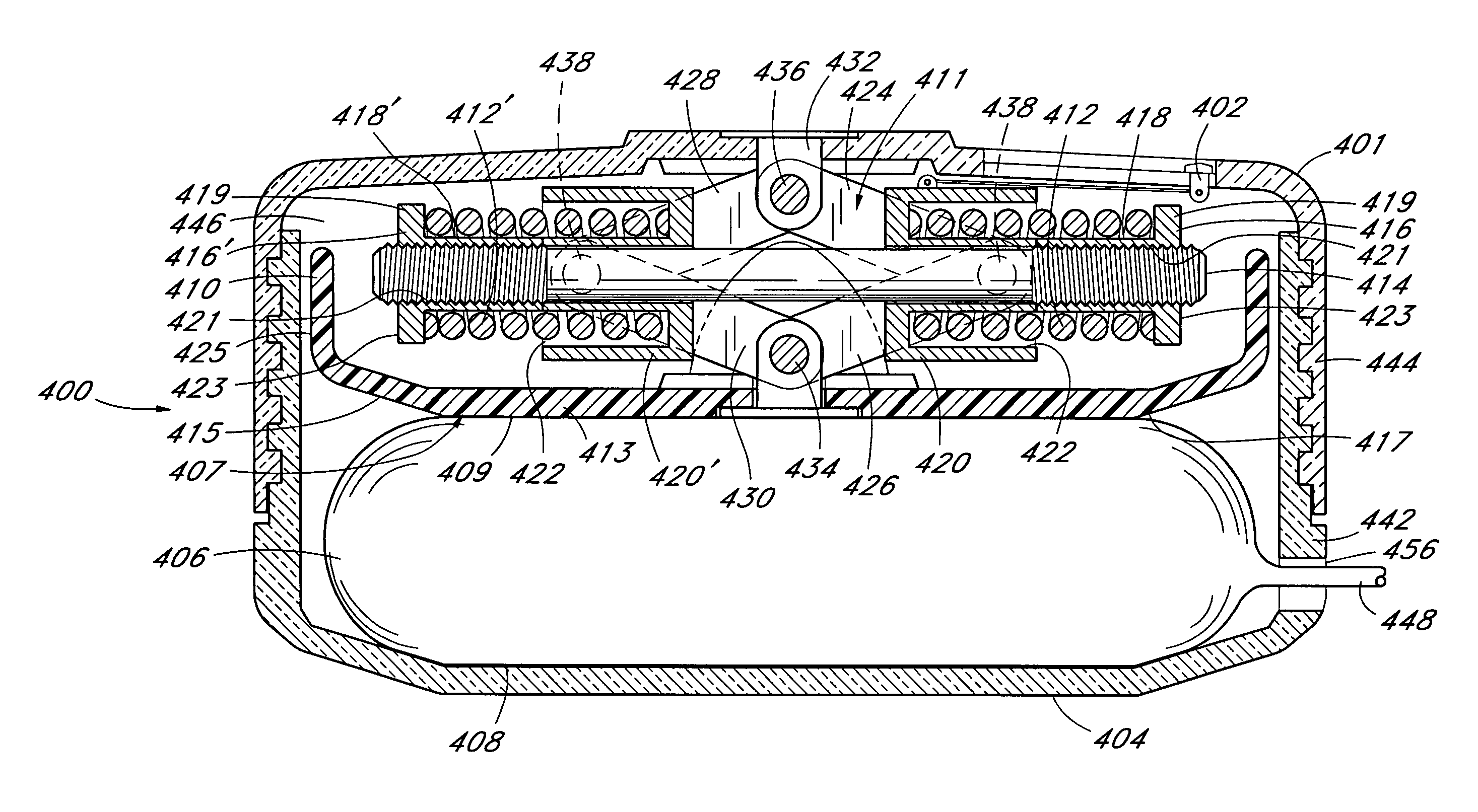
[0244]A platen was constructed in accordance with the embodiment illustrated in FIGS. 52-55, having springs 412 and 412′ comprised of music wire having a wire diameter of approximately 0.085 inch. Springs 412 and 412′ had an outside diameter of about 0.5 inches, a spring constant of approximately 111 lbs. per inch, and were approximately 1.7 inches long in the uncompressed state and approximately 0.9 inch long in the fully compressed state, as shown in FIG. 54. The sum of the axial travel of springs 412 and 412′ was approximately 0.7 inch between the compressed state as shown in FIG. 53 at the beginning of the dispensation cycle and the state shown in FIG. 54 at the end of the dispensation cycle. The springs were preloaded to about 35 lbs. on each side, and were measured to generate a total spring force of about 160 lbs. Blocks 420 and 420′ were constructed from DELRIN, available from DuPont. The length of each of the four link arms was about 0.8 inches from piv...

experiment 2

Testing the Platen Pump

[0245]A 50 cc medication bag 406 was inserted in the platen pump of Experiment 1 and the output fluid pressure from the medication bag 406 was measured as the volume in the medication bag 406 decreased over the dispensation cycle. Table I below illustrates the data accumulated from this experiment.

[0246]

TABLE IVolume Expelled fromOutput FluidMedication Bag (cc)Pressure (psi)05.0.55.015.025.035.045.055.0105.0155.05205.1255.1305.1355.1404.9542.54.6454.45464.25474.1483.948.53.5492.4500

[0247]The data obtained from the above experiment is reproduced in FIG. 56, which plots the volume of medication dispelled in cubic centimeters versus the output pressure in lbs / sq. in. The percent change in output pressure versus the volume expelled is illustrated in FIG. 57. FIG. 57 illustrates the remarkably steady output pressure of the medication contained in medication bag 406 during the dispensation cycle produced by the platen pump 400.

experiment 3

100 cc Volume Test

[0248]In Experiment 3, the 50 cc medication bag 406 was replaced with a 100 cc medication bag. The experiment conducted in Experiment 2 above was repeated and the following data was recorded.

[0249]

TABLE IIVolume Expelled fromOutput FluidMedication Bag (cc)Pressure (psi)05.154.6104.7204.75304.75404.6504.55604.4704.2803.95903.6953.4992.91000

[0250]FIG. 58 illustrates the output pressure over the dispensation cycle. FIG. 59 illustrates the percent change in pressure over the dispensation cycle.

[0251]Increasing the volume of medication in the medication bag 406 from 50 cc to 100 cc remarkably did not dramatically affect the change in pressure over the dispensation cycle on the medication bag 406.

[0252]Referring to FIGS. 61-65, a fluid container 500 is provided which may be readily used with any of the previously disclosed embodiments of the platen pump. Preferably, the fluid container 500 consists of a collapsible medication reservoir or bag 510 in fluid communication w...


PUM


Abstract

An infusion pump for expelling a fluid from a collapsible fluid reservoir to a patient. The pump includes a housing having a chamber therein for receiving the fluid reservoir. A first wall is provided on the housing for contacting the fluid reservoir, and a second wall is movable from a first position distanced from the first wall to form the chamber therebetween, and a second position relatively closer to the first wall. Advancing the movable wall from the first position to the second position expels fluid from the collapsible reservoir at a substantially constant rate by applying increasing force on the fluid reservoir through the dispensation cycle. Preferably, the first and second walls are provided with non-planar complementary surface configurations for contacting the collapsible reservoir. Retraction mechanisms for retracting the movable wall from the second position to the first position, and user readable indicium of the status of the dispensation cycle are also disclosed.

Description

[0001]This application is a divisional of application Ser. No. 08 / 876,180 filed Jun. 23, 1997, now U.S. Pat. No. 6,251,098 issued Jun. 26, 2001, which is a continuation of application Ser. No. 08 / 763,875, filed Dec. 11, 1996, abandoned, which is a continuation of application Ser. No. 08 / 385,083, filed Feb. 7, 1995, abandoned, which is a continuation of application Ser. No. 08 / 008,790, filed Jan. 22, 1993, abandoned, which is a continuation-in-part of application Ser. No. 07 / 898,958 filed Jun. 15, 1992, abandoned, which is a continuation-in-part of application Ser. No. 07 / 824,855 filed Jan. 24, 1992, now U.S. Pat. No. 5,911,716 issued Jun. 15, 1999.FIELD OF THE INVENTION[0002]This invention relates to a drug delivery system, and, more particularly, to a fluid pump configured to deliver fluid at a relatively constant flow rate.BACKGROUND OF THE INVENTION[0003]Many drugs in the healthcare field are administered to a patient on a continuous basis. Continuous delivery of a drug to a pati...

Claims


Application Information

Patent Timeline
IPC IPC(8): B65D35/28A61M1/00A61M5/42A61M5/148
CPCA61M5/148Y10S128/12Y10S128/13Y10S128/24
Inventor RAKE, KENNETH W.JUDGE, ORVIL L.EARHART, DONALD M.MCPHEE, CHARLES J.
Owner BMR MEDICAL LTDA
Why Eureka
Try Eureka