

Resonator element, resonator device and electronic device
- Summary
- Abstract
- Description
- Claims
- Application Information
AI Technical Summary
Benefits of technology
Problems solved by technology
Method used
Image

Examples
first embodiment
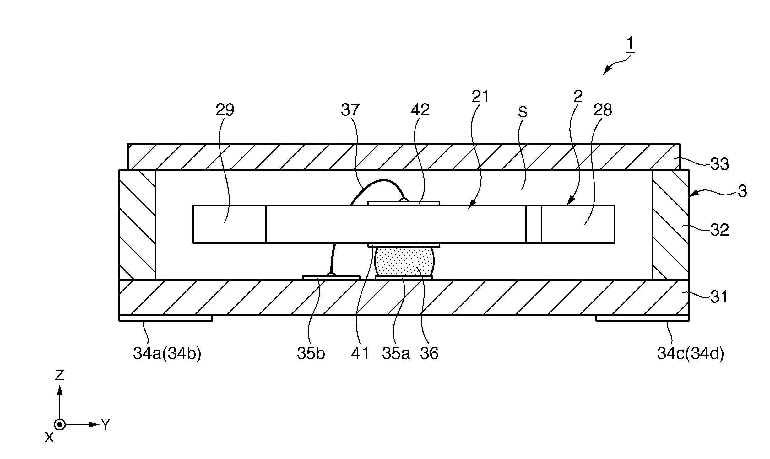
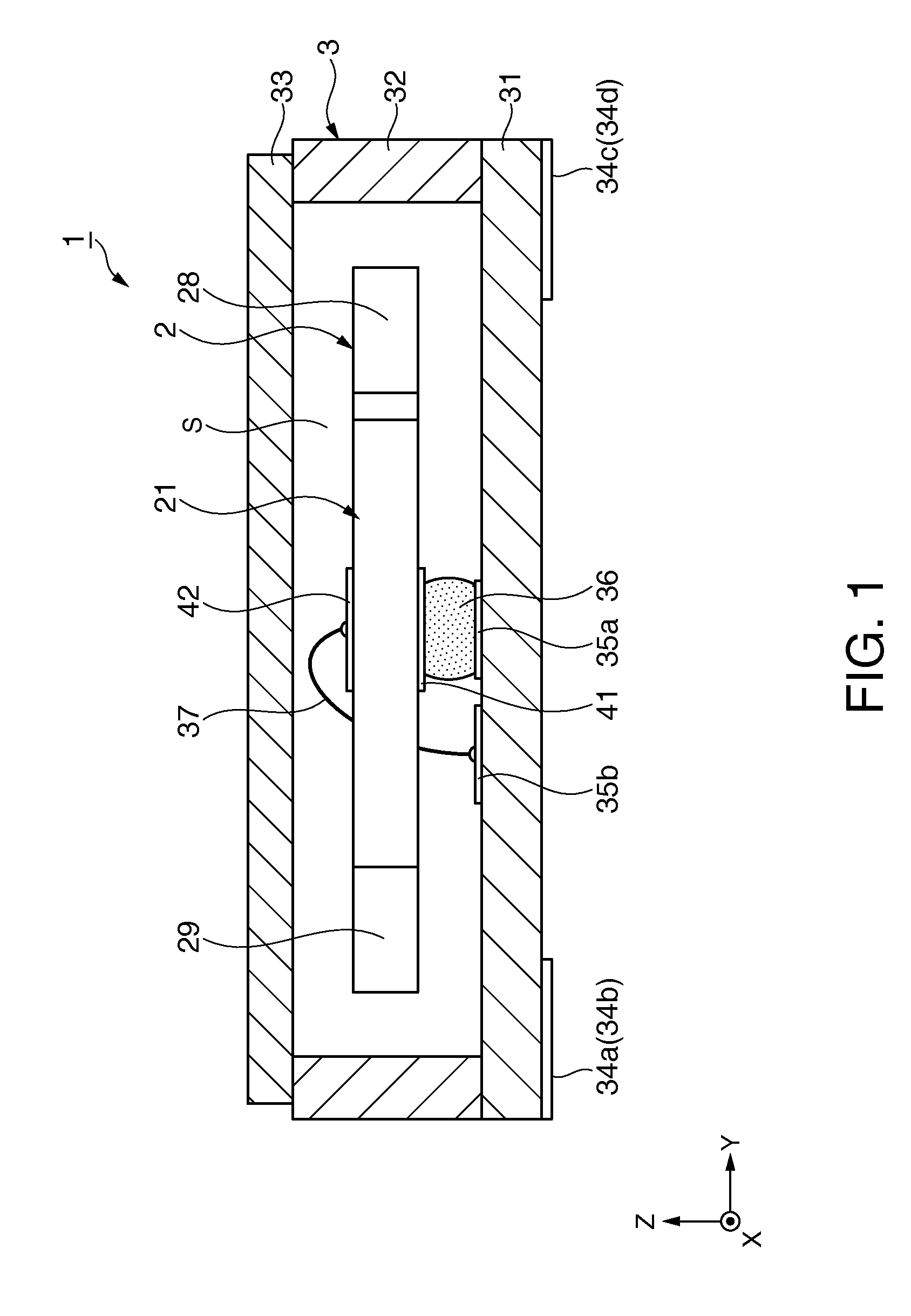
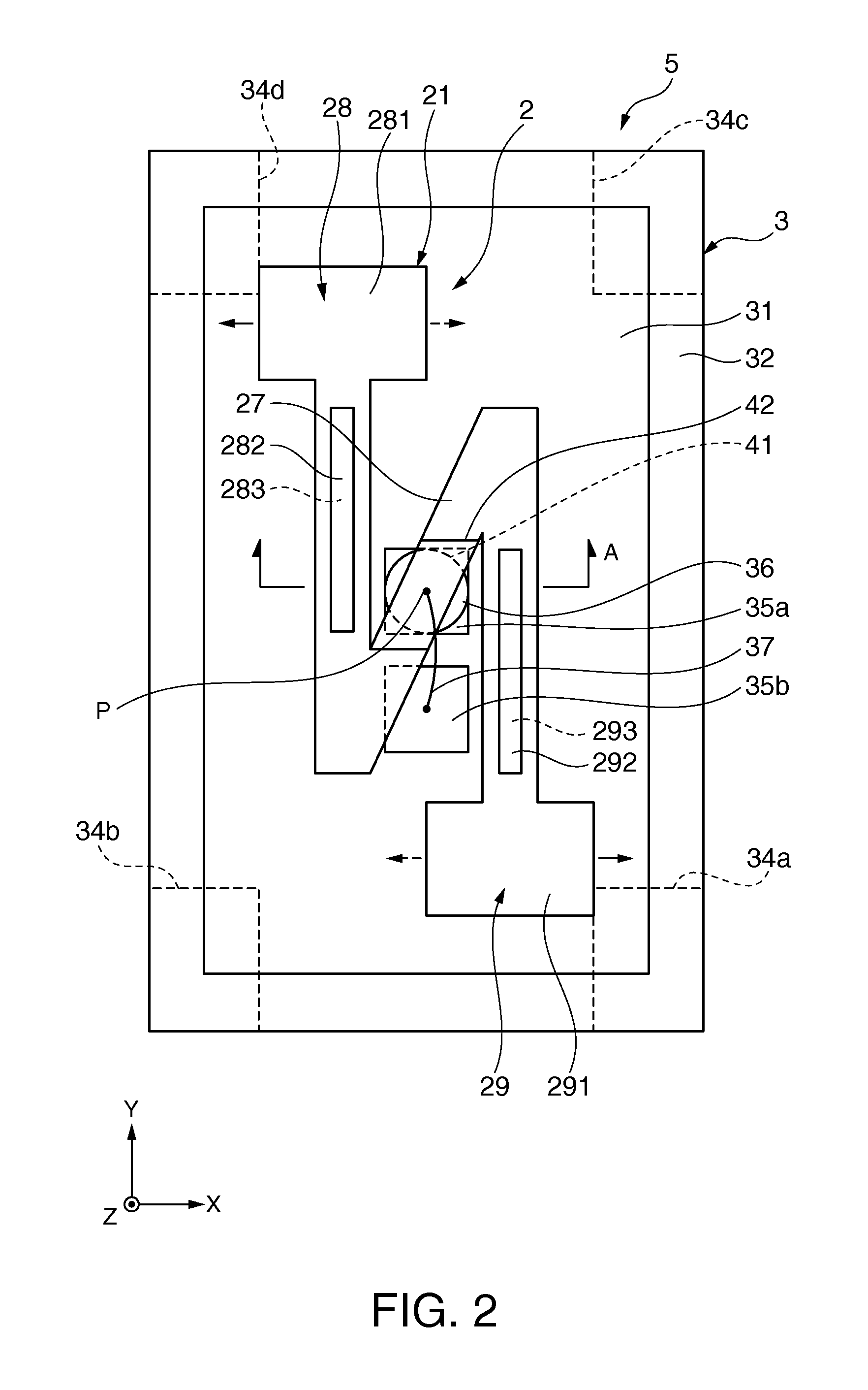
[0050]FIG. 1 is a cross-sectional view illustrating the resonator device of according to a first embodiment of the invention, FIG. 2 is a top plan view illustrating a resonator element included in the resonator device that is illustrated in FIG. 1, FIG. 3 is a cross-sectional view taken along line A-A in FIG. 2 and FIGS. 4A and 4B are top plan views illustrating a function of the resonator element shown in FIG. 2.
[0051]In each of FIGS. 1 to 4, for convenience sake of description, X-axis, Y-axis and Z-axis are illustrated as three axes orthogonal to each other. Hereinafter, a direction (a second direction) that is parallel to the X-axis is referred as the “X-axis direction”, a direction (a first direction) that is parallel to the Y-axis is referred as the “Y-axis direction” and a direction (a third direction) that is parallel to the Z-axis is referred as the “Z-axis direction”. Also, in the description below, for convenience of description, an upper side in FIG. 1 is referred as “upp...
second embodiment
[0106]Next, the second embodiment of the resonator device according to the invention will be described.
[0107]FIG. 5 is a top plan view illustrating the resonator device of a second embodiment according to the invention.
[0108]Hereinafter, description will be given regarding the resonator device of the second embodiment focused on differences from the above described embodiment and description of identical items will not be repeated.
[0109]The resonator device of the second embodiment is similar to that of the first embodiment except that the constitution of the base portion of the resonator element is different. Also, in FIG. 5, the constituent elements similar to those of above described embodiment are given similar reference numbers.
[0110]A resonator device 1A of the embodiment has a resonator element 2A that is accommodated within the package 3 as shown in FIG. 5.
[0111]The resonator element 2A has a vibrating substrate 21A, and excitation electrode groups and connection electrodes ...
third embodiment
[0127]Next, the third embodiment of the resonator device according to the invention will be described.
[0128]FIG. 6 is a top plan view illustrating the resonator device of a third embodiment according to the invention.
[0129]Hereinafter, description will be given regarding the resonator device of the third embodiment focused on difference from the above described embodiment and the same articles thereof will not be described repeatedly.
[0130]The resonator device of the third embodiment is substantially the same as that of the first embodiment except that the constitution of the base portion and the shape of the tip end portion of each of resonating arms are different. Also, the resonator device of the third embodiment is substantially the same as that of the second embodiment except that the shapes of the tip end portion of each of resonating arms are different. In FIG. 6, the constituent elements similar to those of above described embodiment are given similar reference numbers.
[0131...
PUM
 Abstract
Description
Claims
Application Information